
Near-field effect error analysis method

A technology of error analysis and near-field effect, applied in special data processing applications, instruments, electrical digital data processing, etc.

Active Publication Date: 2014-09-24
UNIV OF ELECTRONICS SCI & TECH OF CHINA
View PDF2 Cites 18 Cited by
  • Summary
  • Abstract
  • Description
  • Claims
  • Application Information

AI Technical Summary

Problems solved by technology

The U.S. Army Advanced Simulation Center (ASC) has successively built hardware-in-the-loop simulation systems in the microwave band and two millimeter wave bands. my country has also built various radio frequency simulation centers, but there is still a gap with the United States, Russia and other countries in general.

Method used


Image

  • Near-field effect error analysis method
  • Near-field effect error analysis method
  • Near-field effect error analysis method

Examples


Embodiment Construction

[0036] The present invention will be further described in detail below in conjunction with test examples and specific embodiments. However, it should not be understood that the scope of the above subject matter of the present invention is limited to the following embodiments, and all technologies realized based on the content of the present invention belong to the scope of the present invention.

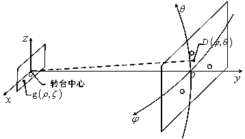
[0037] like figure 1 , the left side is the aperture plane of the receiving antenna, and the point O' is the center of the turntable. On the right is a triad in the target array with O at its center. The simulated target is D, using the angle between O'D and O'O to represent the location of the target. Two coordinate systems are used in this algorithm, and the two coordinate systems can be converted to each other through a certain corresponding relationship. The definitions of the two coordinate systems are introduced below.

[0038] In the spherical coordinate system, with the ...


PUM


Abstract

The invention relates to a near-field effect error analysis method and belongs to the field of radio frequency simulation. Conventional work such as three-element array antenna near-field effect error analysis in China is all based on analytic methods, which are simple, but cannot achieve accurate results and be applicable in an unlimited frequency range. Therefore the near-field effect error analysis method aims to meet the requirements on high frequency and high precision in radio frequency simulation. According to practical application, the near-field effect error analysis method starts with three array element of a three-element array, develops a computational electromagnetic numerical method, combines electromagnetic simulation software to simulate the near-field effect of a three-element array antenna simultaneously, an azimuth-angle and pitch-angle near-field effect error correction table, and obtains a correct target recurrence position through near-field effect error correction. The near-field effect error analysis method is simple and easy and meets the requirements on high frequency and high precision in radio frequency simulation.

Description

technical field [0001] The invention relates to a radio frequency guidance simulation system, and mainly relates to a simulation target position error analysis method caused by near-field effect errors of three array elements. Background technique [0002] Array radio frequency target simulation has the advantage of being convenient for simulating complex targets and environments, and it is a simulation method that has been adopted both at home and abroad. The application of this technology abroad has been relatively mature. The U.S. Army Advanced Simulation Center (ASC) has successively built hardware-in-the-loop simulation systems for microwave bands and two millimeter wave bands. my country has also built various radio frequency simulation centers, but there is still a gap between them and the United States, Russia and other countries in general. Through years of research in China, the working principle, basic design requirements and methods of this type of system have b...

Claims


Application Information

Patent Timeline
Patent Type & Authority Applications(China)
IPC IPC(8): G06F17/50
Inventor 喻梦霞杨苏松刘地凯
Owner UNIV OF ELECTRONICS SCI & TECH OF CHINA
Learn More