Ion mobility spectrometer

A technology of ion mobility and ions, applied in mass spectrometers, dynamic spectrometers, instruments, etc., can solve problems such as ion packet overlap, restricted combination, and data interpretation confusion

Inactive Publication Date: 2014-09-24
LECO CORPORATION
View PDF10 Cites 10 Cited by
  • Summary
  • Abstract
  • Description
  • Claims
  • Application Information

AI Technical Summary

Problems solved by technology

However, this method requires ion packets to overlap and can lead to confusion in data interpretation
[0006] In summary, state-of-the-art IMS

Method used


Image

  • Ion mobility spectrometer
  • Ion mobility spectrometer
  • Ion mobility spectrometer

Examples


Embodiment Construction

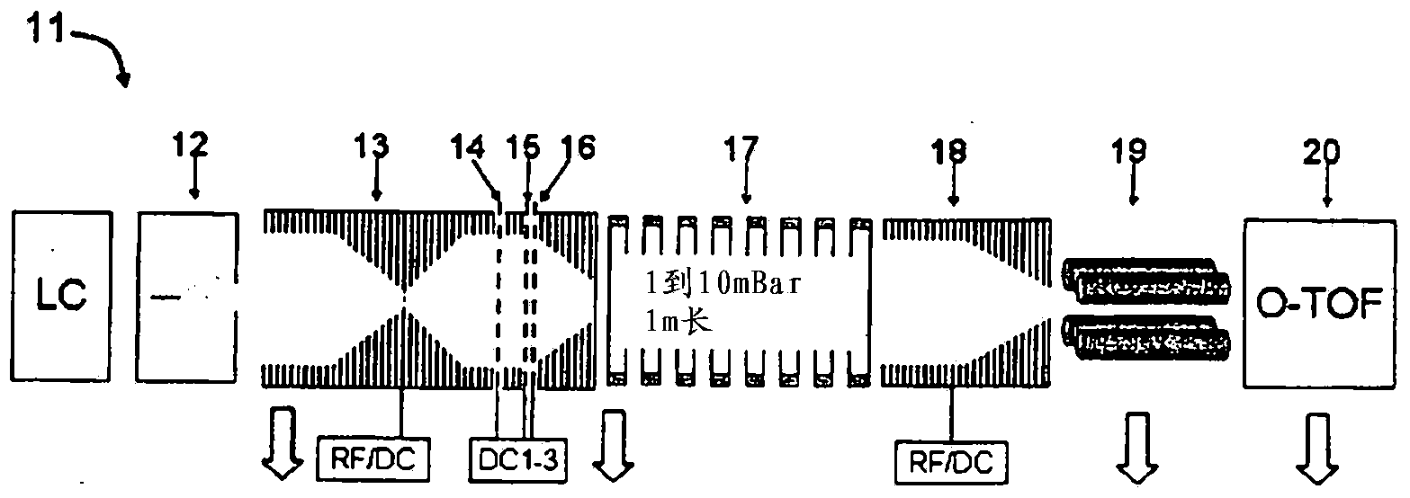
[0030] Referring to FIG. 1 , there is shown a prior art (Anal. Chem., 2008, v.80, pp.612-623, incorporated herein by reference) tandem 11 ion mobility spectrometer (IMS)— - A time-of-flight mass spectrometer (TOF MS) comprising: an ion source 12; an hourglass-shaped ion funnel 13 connected to an RF signal with overlapping axial DC gradients, included between the funnel plates; connected to a switched DC signal Three grids 14, 15 and 16 for ion gating; ion drift tube 17 filled with gas at pressures from 1 to 10 mbar; second ion funnel 18 for converging ion flow; a differentially pumped quadrupole ion guide 19 at an air pressure of 100 mTorr; and a differentially pumped time-of-flight mass spectrometer 20 with orthogonal acceleration. Pumping is shown by white arrows. Some of the RF and DC supplies are shown by boxes. An electrospray (ESI) ion source is shown through a schematic view of the ESI droplet beam, with a gas injector passing through the source - through the light co...


PUM


Abstract

A method and apparatus are disclosed for improving ion mobility spectrometry by using a fast and spatially wide ion gate based on local RF field barrier opposed to a switching DC field. The improvement accelerates the ion mobility analysis and improves charge throughput and dynamic range of the IMS. The invention is particularly suited for rapid dual gas chromatography. In one important embodiment, the accelerated IMS is coupled to a multi- reflecting time-of-flight mass spectrometer with a fast encoded orthogonal acceleration. There are described methods of comprehensive and orthogonal separation in multiple analytical dimensions.

Description

technical field [0001] The present invention relates generally to the field of ion mobility spectrometry and improved ion mobility spectrometry for coupling multidimensional gas chromatography and mass spectrometry. Background technique [0002] Ion mobility spectrometry (IMS) is widely used to analyze ionic compounds based on their mobility, which is a function of ion charge, mass, and shape. A typical IMS includes an ion source for soft ionization of analyte compounds, an ion gate (usually a Tyndal gate) to form short ion packets, a gas-filled drift tube for ion separation in an electrostatic field, and measurement of time-dependent signals The collector (collector). As an independent analytical technique, IMS has low resolution (50-100). IMS is primarily viewed as a low-cost handheld detector of toxic volatile compounds, with a detection limit that can be enhanced by specific ion-molecular reactions with dopant vapors. In recent years, IMS has been coupled with gas chr...

Claims


Application Information

Patent Timeline
IPC IPC(8): G01N30/72H01J49/42
CPCG01N27/622H01J49/406G01N30/72G01N27/623G01N30/7206H01J49/0031
Inventor A·N·维伦奇科夫
Owner LECO CORPORATION
Why Eureka
Try Eureka