
Time-of-flight mass spectrometer system
a mass spectrometer and time-of-flight technology, applied in mass spectrometers, stability-of-path spectrometers, separation processes, etc., can solve the problems of low duty cycle, unsatisfactory tofms, and affecting the performance of tofms, so as to reduce space and cost requirements
Patent Information
- Authority / Receiving Office
- US · United States
- Patent Type
- Patents(United States)
- Current Assignee / Owner
- Publication Date
- 2005-03-22
- Estimated Expiration
- Not applicable · inactive patent
Smart Images
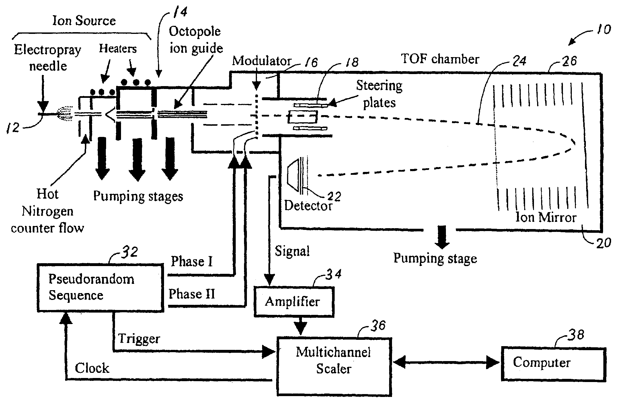
Figure 1 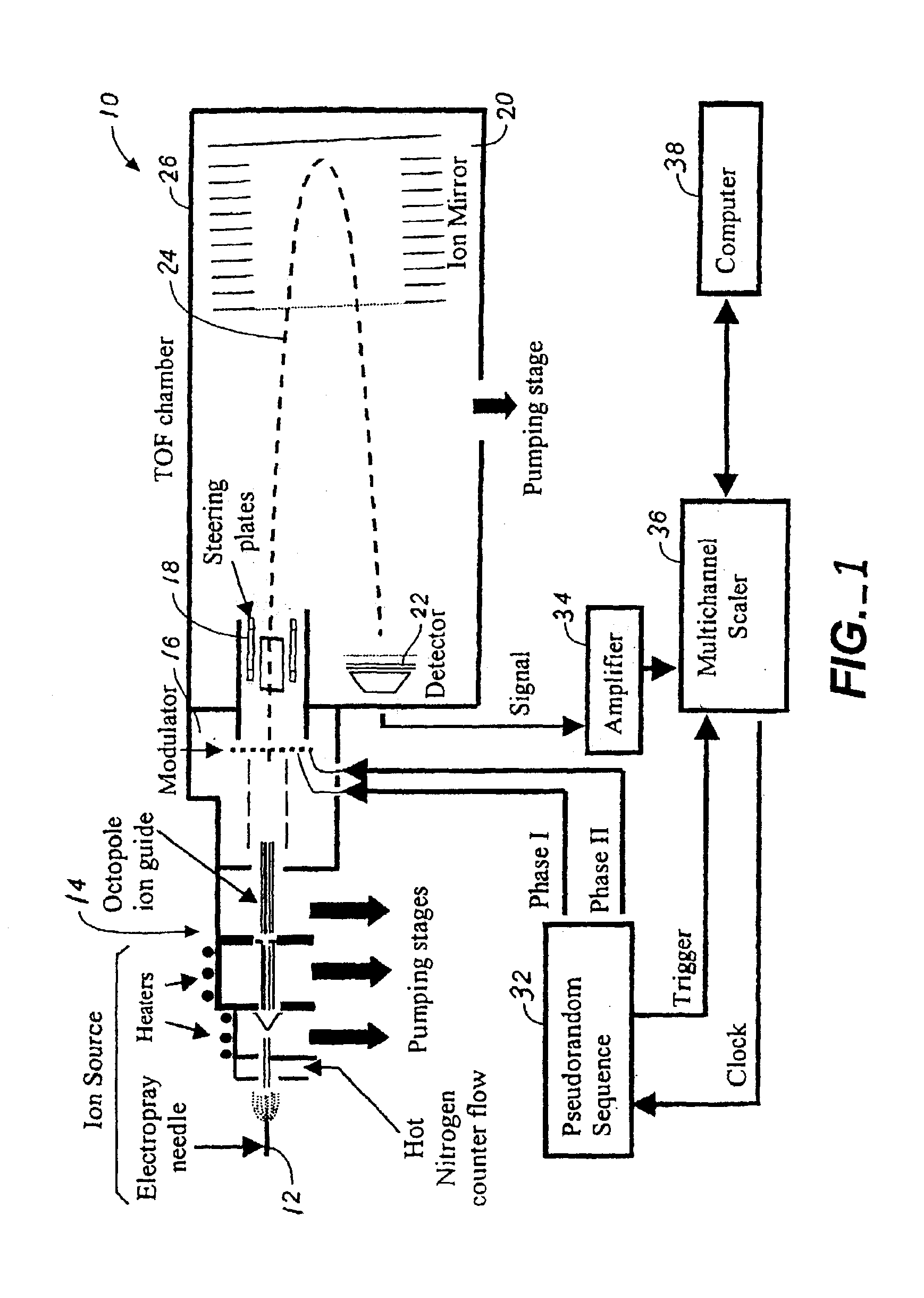
Figure 2 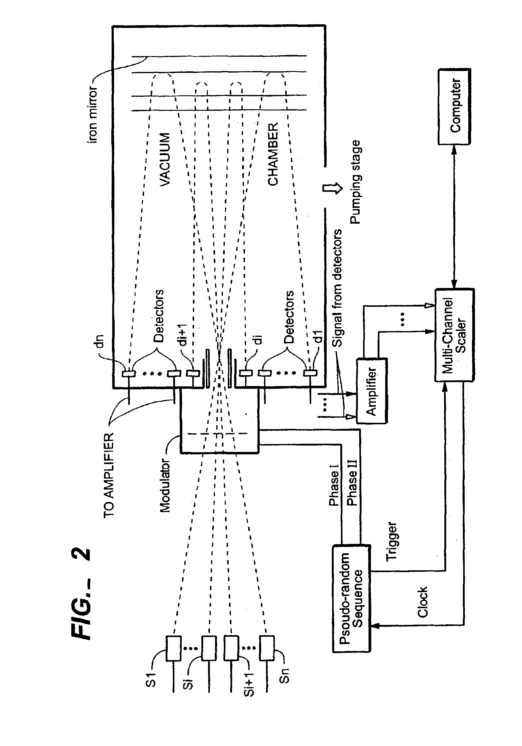
Figure 3
Abstract
Description
BACKGROUND OF THE INVENTIONThis invention relates in general to mass spectrometers and in particular to time-of-flight mass spectrometers.Time-of-flight (“TOF”) analysis has found widespread application because particle velocity, momentum, and mass can be determined from an experiment by constraining the appropriate parameters for the experiment. Time-of-flight mass spectrometers (“TOFMSs”) have the very desirable characteristic of high ion transmission, high repetition rate, good resolution and modest cost, which makes them very attractive as a mass sensitive detector in analytical instrumentation. Such applications were until recently somewhat hampered by the fact that most analytical ion sources produce continuous ion beams. The pulsed operation of a conventional TOFMS causes a rather low duty-cycle and TOFMS could not live up to its promises. For more detailed description of the state of the art of TOFMS, please see “The New Time-Of-Fight Mass Spectrometry,” by Robert J. Cotter,...
Examples
Embodiment Construction
FIG. 1 is a block diagram of TOFMS system 10 to illustrate one embodiment of the invention with an electrospray ionization source 12. Ions supplied by an electrospray needle 12 are passed through pumping stages equipped with heaters, and hot nitrogen counterflow, an occtopole ion guide 14. Ions are accelerated after the ion guide to reach a modulator 16 comprising an array of elongated electrical conductors (such as a linear array of wires). Preferably the conductors are arranged in a plane orthogonal to the direction of the ion beam emanating from the pumping stage or occtopole ion guide 14, although in another embodiment, the conductors may be arranged in a non-orthogonal plane or in multiple planes. After passing through the modulator 16, the preferably parallel beam is steered with the help of two sets of deflection plates 18, through the ion mirror 20 and onto the detector 22.
In a manner different from the prior art scheme in the patent to Myerholtz et al. described above, when...