
X-ray recording system for x-ray imaging at high image frequencies of an object under examination by way of direct measurement of the interference pattern

A shooting system and interference pattern technology, which can be used in radiological diagnostic instruments, radiation detection devices, medical science, etc., and can solve problems such as inappropriate mechanical movement and real-time imaging

Inactive Publication Date: 2014-10-01
SIEMENS AG
View PDF10 Cites 13 Cited by
  • Summary
  • Abstract
  • Description
  • Claims
  • Application Information

AI Technical Summary

Problems solved by technology

[0027] The implementation of this method presents many challenges, but in particular has one very significant disadvantage:
Also such a structure due to the analytical grating G 2 The mechanical movement is not suitable for real-time imaging or imaging with a higher image frequency such as 15 images per second (B / s) or 60 to 100 B / s

Method used


Image

  • X-ray recording system for x-ray imaging at high image frequencies of an object under examination by way of direct measurement of the interference pattern
  • X-ray recording system for x-ray imaging at high image frequencies of an object under examination by way of direct measurement of the interference pattern
  • X-ray recording system for x-ray imaging at high image frequencies of an object under examination by way of direct measurement of the interference pattern

Examples


Embodiment Construction

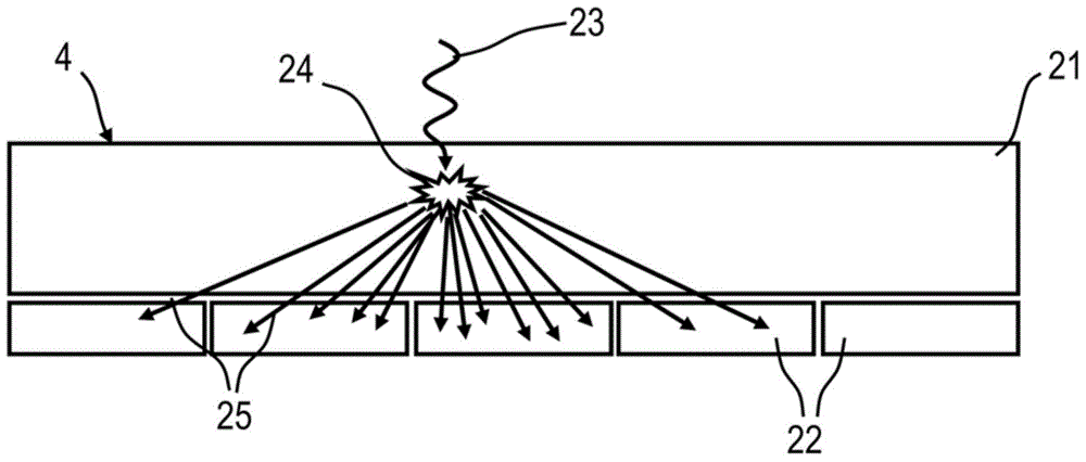
[0059] exist image 3 3 schematically shows a sectional view (cross section) of an x-ray image detector 4 with a detector layer 21 of conventional material and an underlying layer with photosensitive detector pixels 22 . The x-ray quanta 23 strikes the x-ray imaging detector 4 and due to the absorption of the x-ray quanta in the excited phosphor of the detector layer 21 produces a primary event 24 , whereby a secondary quantum 25 is emitted. These emitted secondary quanta are detected by light-sensitive detector pixels 22 .

[0060] Figure 4 Now shown as pixel signal 26 according to image 3 The possible distribution of the output signal of the pixel signal, the pixel signal can be an analog voltage or a digital value, and a fitting function 27 is applied as a match on the voltage or value, and the match is a mathematical optimization method, so that for a series of The measured data determine or estimate unknown parameters of a model or predetermined function. The maximu...


PUM


Abstract

An x-ray recording system is disclosed for x-ray imaging of an object under examination by way of direct measurement of an interference pattern, especially for differential, real-time capable phase-contrast imaging. In at least one embodiment, the system includes with at least one x-ray emitter for creating quasi-coherent x-ray radiation; an x-ray image detector, including a detector layer and detector pixels arranged in a matrix; and a diffraction or phase grating, disposed between the object under examination and the x-ray image detector, configured to create an interference pattern, directly detectable in the nth Talbot order by an x-ray image detector with a very high achievable local resolution, which amounts to at least half the wavelength of the interference pattern in accordance with the Nyquist theory arising in the nth Talbot order.

Description

technical field [0001] The invention relates to an x-ray imaging system for x-ray imaging of an examination object by direct measurement of an interference pattern, in particular for differential, real-time-capable phase-contrast imaging, comprising: at least one for generating quasi-coherent x-ray radiation An x-ray emitter, an x-ray image detector with a detector layer and detector pixels arranged in a matrix, a diffraction or phase grating arranged between the examination object and the x-ray image detector and generating an interference pattern. Background technique [0002] Differential phase-contrast imaging is an imaging method that has gained a lot of attention for some time, especially in Talbot-Lau interferometer arrangements. For example in the publication F. Pfeiffer et al. [1], "Hard X-ray dark-field imaging using a grating interferometer", Nature Materials 7, pp. 134 to 137, it is described that by means of a conventional X-ray tube, three An interferometric s...

Claims


Application Information

Patent Timeline
Patent Type & Authority Applications(China)
IPC IPC(8): A61B6/00
CPCA61B6/484A61B6/42A61B6/4208A61B6/4233A61B6/4441A61B6/4458A61B6/504
Inventor P.伯恩哈特M.斯帕恩
Owner SIEMENS AG
Learn More