Combined tools for machining holes and machining methods

A technology for combining tools and processing holes, which is applied in the direction of manufacturing tools, metal processing equipment, drilling accessories, etc., can solve the problems of low precision and cumbersome adjustment of the position of the tool tip, etc., and achieves improved processing efficiency and easy expansion. Hole processing and the effect of increased production time

Active Publication Date: 2014-10-01
NANJING MEISHAN METALLURGY DEV
View PDF6 Cites 6 Cited by
  • Summary
  • Abstract
  • Description
  • Claims
  • Application Information

AI Technical Summary

Problems solved by technology

In the prior art, when adjusting the height position of the tool tip before or during the process, it is adjusted on the tool holder by adding or subtracting pad blades of different thickne

Method used


Image

  • Combined tools for machining holes and machining methods
  • Combined tools for machining holes and machining methods
  • Combined tools for machining holes and machining methods

Examples


Embodiment 1

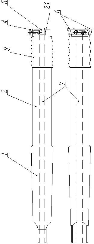
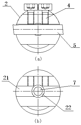
[0027] Such as figure 1 As shown, a combination tool for machining holes includes a tool holder 2 and a cutter head 5, and one end of the tool holder 2 is a Morse taper 1 structure, through which the combination tool can be inserted into the Morse taper of a lathe tailstock or a drilling fixture. There is a square groove 21 at the top of the other end of the cutter bar 2, and the cutter head 5 can be loaded in the square groove, and the cutter head 5 is fastened with two screws 4. The end of the cutter head 5 There is a chip breaker 6 on both sides of the head; there is a through hole 7 in the middle of the tool bar 2, and the coolant can enter from the through hole 7 when machining deep holes. Since the tool rod is relatively slender, in order to ensure the rigidity of the tool rod, the diameter of the through hole 7 cannot be too large. During processing, we found that the diameter of the through hole 7 is slightly smaller than the height of the cutter head 5, so that when t...

Embodiment 2

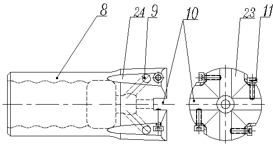
[0030] Such as image 3 , Figure 4 As shown, the second combination tool for machining holes includes a cutter bar 2 and a cutter head body 8 installed on the cutter bar 2. The cutter bar 2 is provided with a through hole along the axial direction, and one end of the tool bar 2 has a Morse taper. There is a wave thread 3 on the outer surface of the handle 1 and the other end (the wave thread here is only a specific example of thread, as long as it is a thread structure that can form a mating connection, it may be applied in this technical solution by those skilled in the art) , the cutter head body 8 has an internal thread that matches the external thread of the cutter bar 2, and the top of the cutter head body 2 has a cross groove 10, and a small cutter head 12 is respectively installed in the four groove bodies of the cross groove 10, and the knife The number of heads 12 is four, which realizes the participation of multiple cutters and multiple blades in the cutting pr...

Embodiment 3

[0034] In the utility model patent "a drilling jig for lathes" (ZL 2007 2 0144284.7) that the inventor applied for and obtained authorization in 2007, a drilling jig for lathes is disclosed, such as Figure 5 As shown, including the clamp body 13, there is a Morse taper hole 16 on the clamp body, and the Morse taper hole 16 is provided with an opening slit 15 to the edge of the clamp body 13, and the Morse taper hole taper hole side of the clamp body is perpendicular to the opening Two screw holes 14 are arranged at intervals in the seam direction, and a clamp screw 17 is installed in the screw holes, and a washer 18 is arranged between the clamp screw 17 and the clamp body 13 .

[0035]The two combination cutters proposed by the present invention can be used in conjunction with the above-mentioned clamps. The processing method of the first cutter is: place the clamp body 13 flatly against the lathe tool holder 20, tighten the tool holder screw rod 19, and place the cutter ...


PUM


Abstract

The invention discloses two kinds of combined tools arranged on lathes for machining holes and machining methods thereof; according to the combined tools for machining holes and the machining methods thereof, the problems that in machining, the existing hole machining methods are large in drill bit consumption, vertical positions of noses of the tools in workpiece holes are inconvenient to adjust and cooling liquid cannot be fully filled can be solved. The combined tool for machining holes comprises a toolbar and a tool bit, wherein one end of the toolbar is provided with a Morse taper shank while the other end is provided with a square groove; the tool bit is installed in the square groove through a fastener; two sides of the end of the tool bit are respectively provided with a chip breaker groove; the toolbar is provided with a through hole along the axis direction; one end, close to the tool bit, of the through hole is provided with a step-shaped hole, and the diameter of the step-shaped hole is more than the width of the tool bit. When the combined tool is used for machining a deep hole, the cooling liquid can be fully filled, so that cutting environment is improved, and service life of the tool and machining quality of product are enhanced; with improvement on the tool bit, compared with the original technology of repairing a waste connecting sleeve by a drill bit, the combined tool is greatly improved in machining efficiency.

Description

technical field [0001] The invention belongs to the technical field of mechanical processing, and in particular relates to a combination cutter for processing holes of two kinds and a method for processing holes by using the cutter. Background technique [0002] Whether it is drilling, reaming or internal thread processing, it is generally necessary to add sufficient coolant. Usually, the coolant is injected on the drill bit or tool holder near the hole. When processing deep holes, the coolant If it cannot enter the cutter head or enters very little, the cooling effect and lubrication effect on the tool and workpiece will be significantly reduced, thereby affecting the service life of the tool and the processing quality of the product. [0003] In the use of drilling tools for blast furnace openings and underground rock drilling, many waste connecting sleeves are often produced due to the large torque resistance. Most of these connecting sleeves are in good condition and...

Claims


Application Information

Patent Timeline
IPC IPC(8): B23B51/00B23B51/06B23B41/02
CPCB23B41/02B23B51/00B23B51/06B23B51/08
Inventor 陈海平宁宇
Owner NANJING MEISHAN METALLURGY DEV
Why Eureka
Try Eureka