Cross-flow fan blade welding robot

A welding robot and cross-flow fan blade technology, applied in the field of cross-flow fan blade welding robots, can solve problems such as the advent of equipment

Active Publication Date: 2014-10-01
SHENZHEN SIJIECHUANG TECH CO LTD
View PDF5 Cites 14 Cited by
  • Summary
  • Abstract
  • Description
  • Claims
  • Application Information

AI Technical Summary

Problems solved by technology

At present, the domestic fully automatic and intelligent technology is still blank, and there is no equipment with the technical characteristics of the present invention, such as welding precision control, welding quality monitoring, stable and reliable operation, etc.

Method used


Image

  • Cross-flow fan blade welding robot
  • Cross-flow fan blade welding robot
  • Cross-flow fan blade welding robot

Examples


Embodiment 1

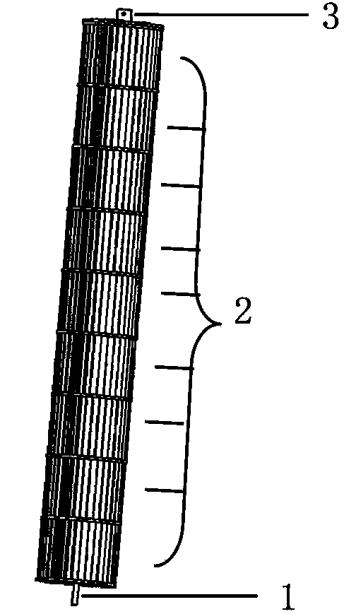
[0061] Example 1 Such as figure 1 As shown, the entire cross-flow fan blade is formed by a single shaft cover 1, a plurality of middle sections 2 and a single end cover 3 which are cascaded in sequence through an ultrasonic welding process. Among them, the shaft cover 1 is at the lowest end and the multiple middle sections 2 (From bottom to top, first to last) is in the middle and end cap 3 is at the top. Unless otherwise specified, the shaft cover, middle section and end cover are referred to as workpieces in the description of the present invention.

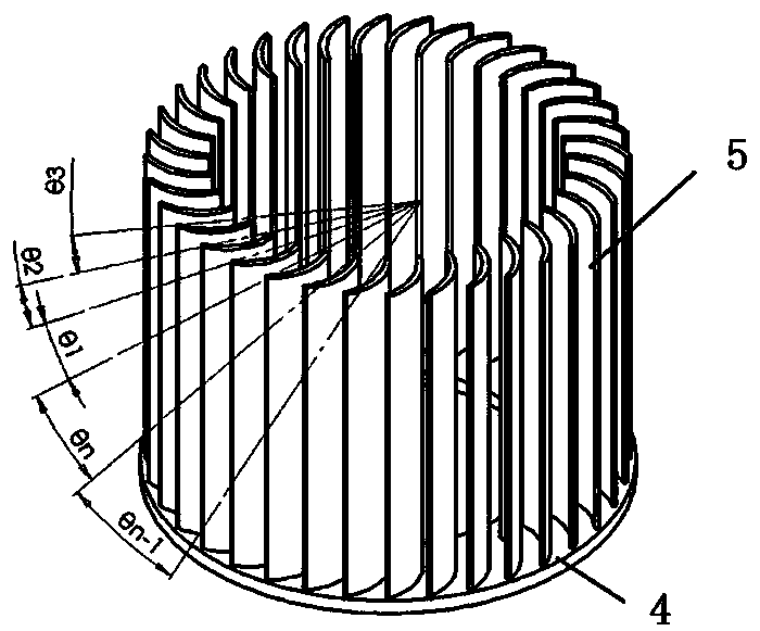
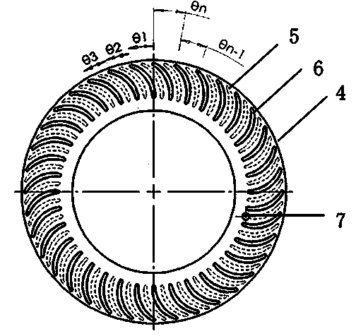
[0062] Such as figure 2 with image 3 The middle section 2 shown is composed of an A circular disk 4 and a plurality of A blades 5. The cross section of the A blade 5 is arc-shaped, and the rear end of the A blade 5 is connected to the lower surface of the circular disk 4, The upper surface of the A circular wheel 4 is provided with the same number of A positioning lobes 6 as the A blades 5, which are used to insert another mi...

Embodiment 2

[0095] Example 2 Picture 10 A preferred embodiment suitable for internal repair end caps is shown. versus Figure 8 In comparison, the difference is that the inner repair end cover belt line feeding mechanism replaces the outer repair end cover vibration plate feeding mechanism 28. The inner repair end cover belt line feeding mechanism includes a storage belt line 33 and a storage belt line 33 For the connected feeding belt line 34, the other embodiments are the same as those in the first embodiment.


PUM


Abstract

The invention discloses a cross-flow fan blade welding robot. The cross-flow fan blade welding robot comprises a material distribution and conveying module, a material grabbing mechanical arm, a pre-positioning module, a feeding module, an ultrasonic welding machine and a material receiving module; the welding robot is used for conveying a workpiece to the material grabbing mechanical arm through the material distribution and conveying module and is primarily shaped and self-centered through being clamped by three clamping claws; then the workpiece is conveyed into the pre-positioning module to realize eight-clamping-claw clamped self-centering and rotary alignment of positioning marks; four-clamping-claw clamped self-centering, compensation of translation errors and rotary angle errors, and blade embedment of soft landing and rotary search are realized by the feeding module, and furthermore, the welding is finished in an ultrasonic welding machine through the clamping self-centering and the clamping force control of four guide rods, two-grade type welding head movement and a digital power supply driven ultrasonic transducer; then the material receiving module is used for taking out a welded finished product and conveying the welded finished product to a material storage belt line. The cross-flow fan blade welding robot has the advantages of rapid welding period, low noises, high yield, short line exchanging time, online real-time quality monitoring, stability and reliability in operation and the like.

Description

technical field [0001] The invention relates to the application field of injection molding ultrasonic welding, in particular to a cross-flow fan blade welding robot. Background technique [0002] The cross-flow fan blade has the characteristics of compact structure, small size, large air flow, uniform horizontal direction, long distance and low noise. It is widely used in low-pressure ventilation occasions such as air conditioners, household appliances, tower fans, and air curtains. The cross-flow fan blade is made of engineering plastics, and the components include a single shaft cover, multiple middle sections, a single outer end cover or an inner end cover. In the current mature manufacturing process, ultrasonic welding is the key process for the manufacture of cross-flow fan blades. It is connected in series by means of ultrasonic welding. Taking the cascade link between the middle sections as an example, before welding, dozens of slender and thin blades at the front e...

Claims


Application Information

Patent Timeline
Patent Type & Authority Applications(China)
IPC IPC(8): B29C65/08
Inventor 王耀明
Owner SHENZHEN SIJIECHUANG TECH CO LTD
Why Eureka
Try Eureka