
Optical fiber filling factice supply system

A technology for filling ointment and supply system, which is applied in pipeline systems, gas/liquid distribution and storage, mechanical equipment, etc., and can solve the problems of ointment pollution, leakage, and increased labor intensity

Inactive Publication Date: 2014-10-01
HANGZHOU FUTONG COMM TECH CO LTD
View PDF7 Cites 7 Cited by
  • Summary
  • Abstract
  • Description
  • Claims
  • Application Information

AI Technical Summary

Problems solved by technology

[0003] In the general optical fiber production and manufacturing process, it is usually to place grease barrels at each production machine station, and then transport the fiber optic grease to the required production equipment through the oil pipeline. However, when replacing the fiber grease barrels, It is necessary to frequently plug and unplug the oil pipeline, which will easily cause fiber grease pollution and leakage during the process, seriously affecting product quality, and frequent replacement of grease barrels increases the labor intensity of the staff, seriously restricting the overall production efficiency of the optical fiber

Method used


Image

  • Optical fiber filling factice supply system
  • Optical fiber filling factice supply system
  • Optical fiber filling factice supply system

Examples


Embodiment Construction

[0027] The core of the present invention is to provide an optical fiber filling ointment supply system, which can avoid frequent replacement of ointment barrels during the optical fiber manufacturing process, reduce labor intensity of staff and improve overall production efficiency.

[0028] In order to enable those skilled in the art to better understand the solution of the present invention, the present invention will be further described in detail below in conjunction with the accompanying drawings and specific embodiments.

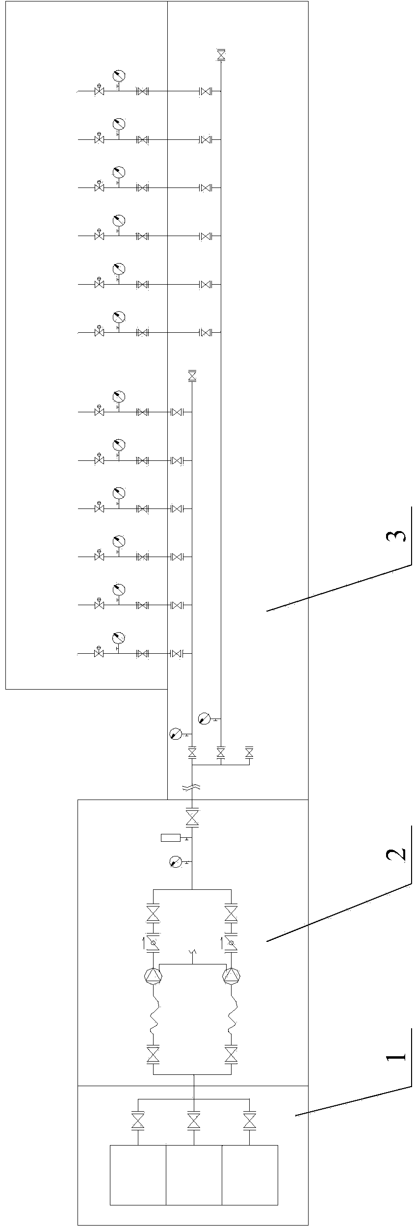
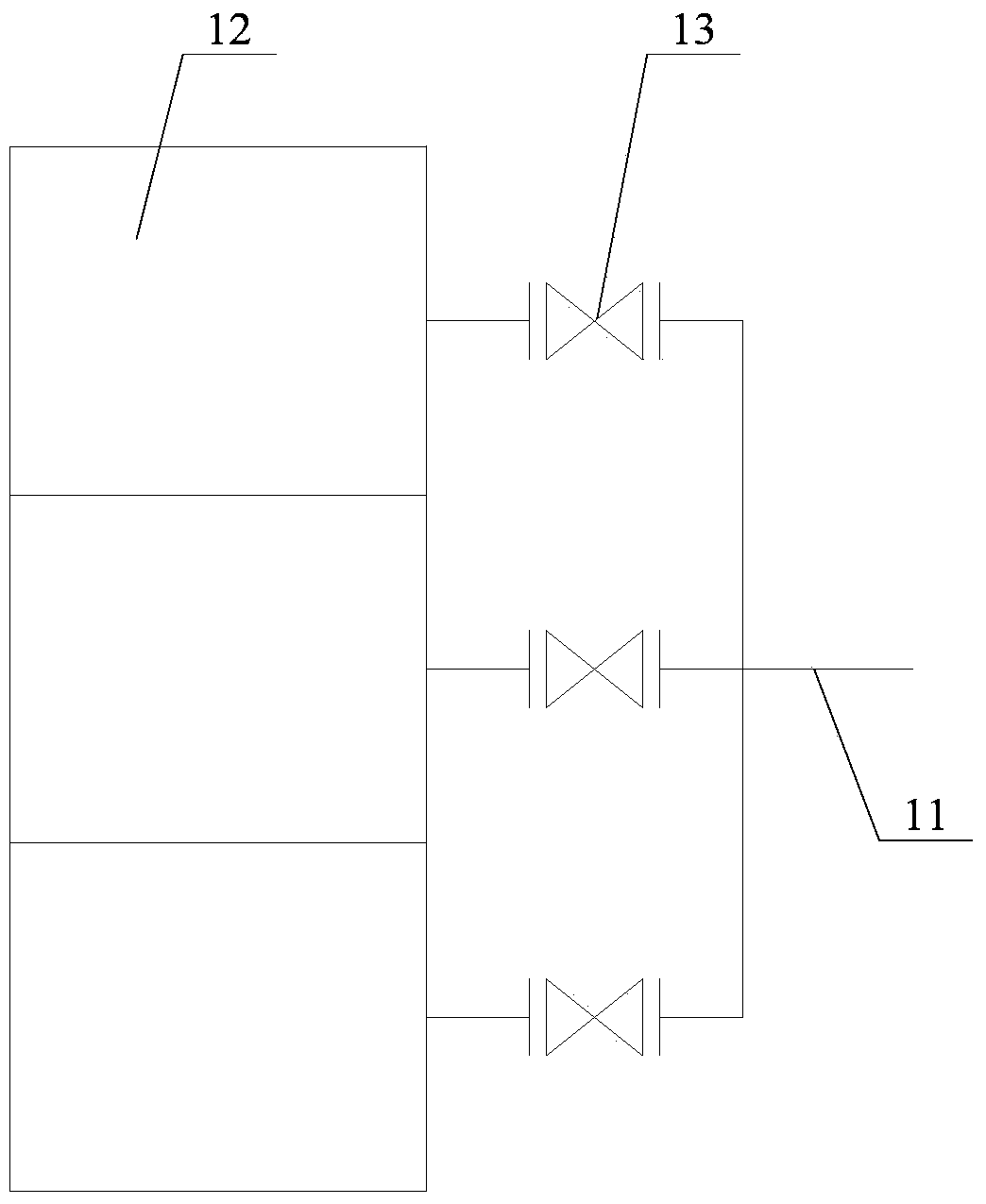
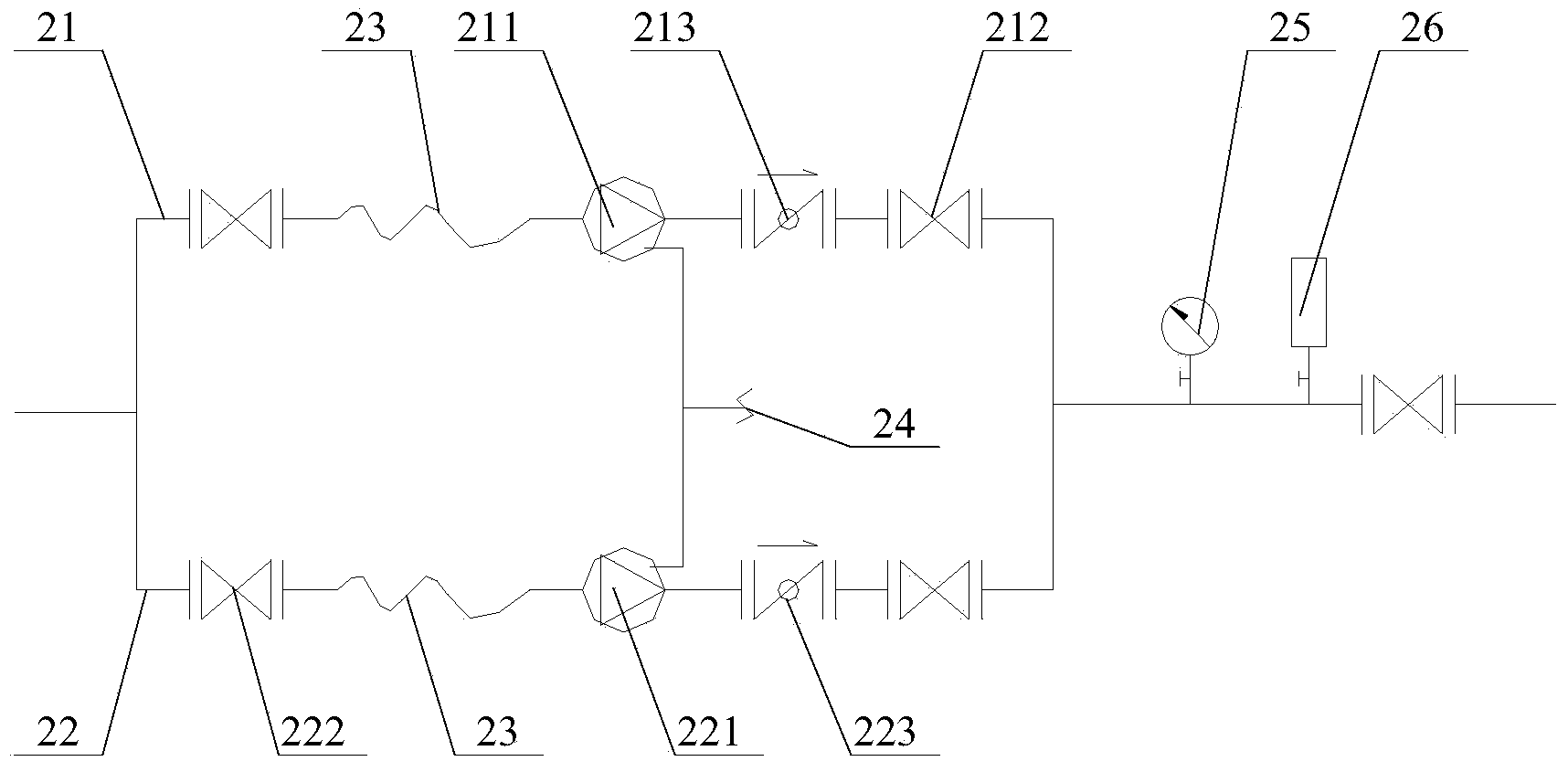
[0029] Please refer to figure 1 , figure 2 , image 3 and Figure 4 , figure 1 An overall schematic diagram of an optical fiber filling grease supply system provided for a specific embodiment of the present invention; figure 2 for figure 1 Schematic diagram of the oil tank area; image 3 for figure 1 Schematic diagram of the medium ointment delivery area; Figure 4 for figure 1 Schematic diagram of the mid-feed terminal area.

[0030] In a ...


PUM


Abstract

The invention discloses an optical fiber filling factice supply system. The optical fiber filling factice supply system comprises a factice barrel area, a factice conveying area and a feed terminal area. A factice barrel is arranged in the factice barrel area. The discharge port of the factice barrel is communicated with an upstream conveying pipeline. An upstream feed valve is arranged on the upstream conveying pipeline. A first midstream conveying pipeline communicated with the upstream conveying pipeline and a downstream conveying pipeline and a second midstream conveying pipeline communicated with the upstream conveying pipeline and the downstream conveying pipeline are arranged in the factice conveying area. A first oil pump is arranged on the first midstream conveying pipeline. A second oil pump is arranged on the second midstream conveying pipeline. The feed terminal area comprises the downstream conveying pipeline communicated with the first midstream conveying pipeline and the second midstream conveying pipeline, and a material storage barrel. A feed branch is communicated between the material storage barrel and the downstream conveying pipeline. A branch feed valve is arranged on the feed branch. By means of the optical fiber filling factice supply system, the factice barrel can be prevented from being frequently replaced in the optical fiber manufacturing process, labor intensity of workers is lowered, and overall production efficiency is improved.

Description

technical field [0001] The invention relates to the technical field of optical fiber filling ointment supply equipment, in particular to an optical fiber filling ointment supply system. Background technique [0002] Optical fiber ointment is commonly known as fiber ointment. Due to the particularity of the optical fiber structure, optical fiber ointment needs to be used to protect its main structure during the production process, and to protect the optical fiber from moisture, lubrication, and shock resistance. Since the optical fiber production process has high requirements on raw materials and environmental cleanliness, it is required that the fiber paste itself is not polluted during the transportation process, and it is forbidden to mix other sundries and not pollute the environment. [0003] In the general optical fiber production and manufacturing process, it is usually to place grease barrels at each production machine station, and then transport the fiber optic greas...

Claims


Application Information

Patent Timeline
IPC IPC(8): F17D1/14F17D3/01
Inventor 徐建飞胡胜平张腊生许增宾李金华华奇江闽西王建军陈曲
Owner HANGZHOU FUTONG COMM TECH CO LTD
Learn More