Instant liquefied fuel gasifying combustion stove

A liquid fuel, combustion furnace technology, applied in the direction of liquid heating fuel, heating fuel, household stove/stove, etc., can solve the problems of liquid leakage, high pressure, bad, etc., achieve uniform fire distribution, improve thermal efficiency, and good heating effect. Effect

Inactive Publication Date: 2014-10-01
邹鑫
View PDF10 Cites 0 Cited by
  • Summary
  • Abstract
  • Description
  • Claims
  • Application Information

AI Technical Summary

Problems solved by technology

However, this kind of liquid fuel burner without gasification has an unsatisfactory combustion effect of the liquid fuel; on the one hand, the mixing of the air and the liquid fuel is insufficient, resulting in insufficient combustion of the liquid fuel, and the utilization rate of the liquid f

Method used


Image

  • Instant liquefied fuel gasifying combustion stove
  • Instant liquefied fuel gasifying combustion stove
  • Instant liquefied fuel gasifying combustion stove

Examples


Embodiment 1

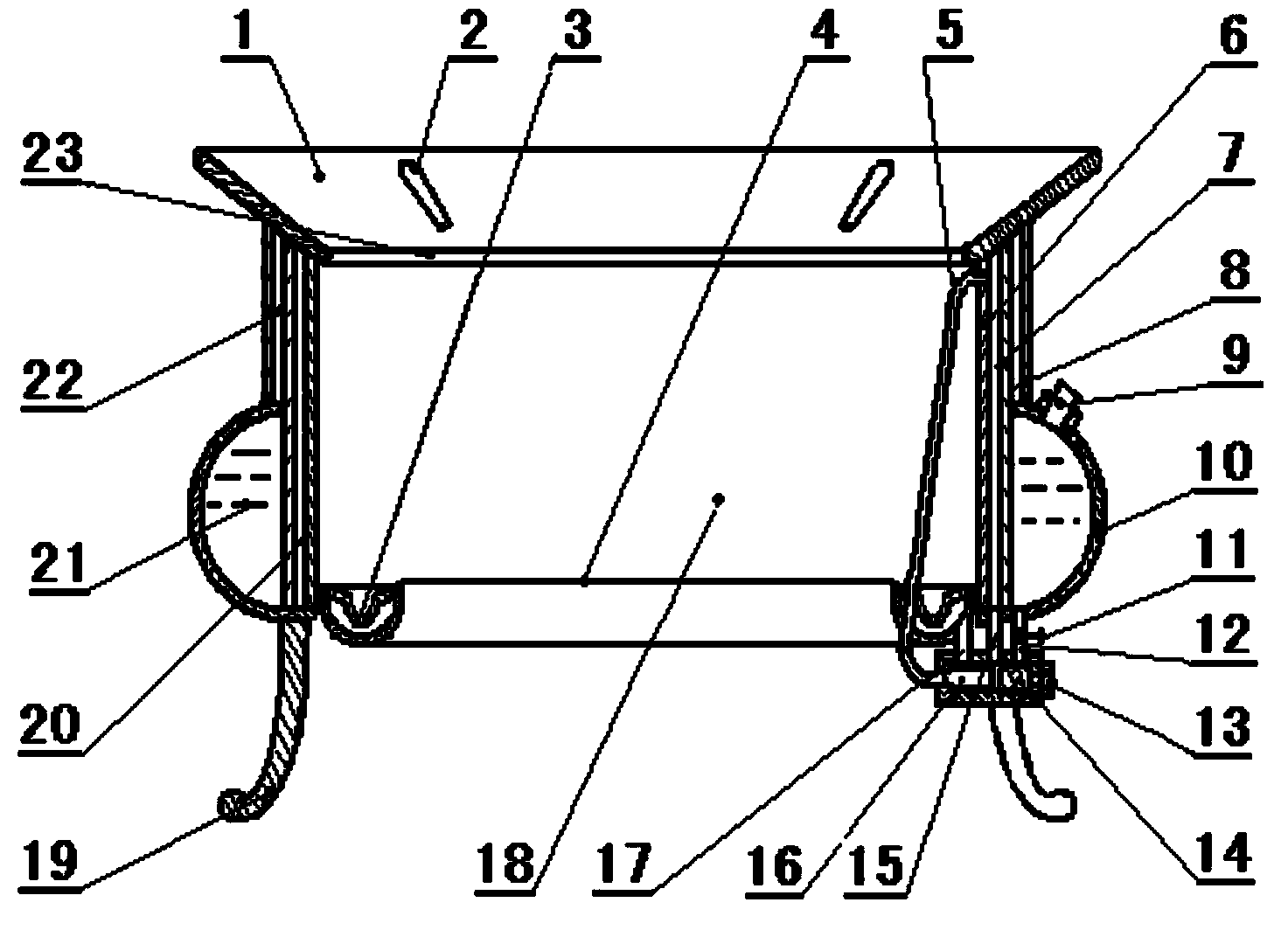
[0029] A small liquid fuel instant gasification combustion furnace, characterized in that: the setting includes: a furnace base 1, a combustion tank ring pipe 4, a gas supply pipe 5, a heat transfer layer 6, a gas-liquid interlayer 7, an insulation layer 8, and a liquid supply ring groove 10. Liquid and gas control valve 13 and stove foot 19; the heat transfer layer 6 is the innermost layer of the combustion furnace, and the heat transfer layer 6 is connected with the combustion groove ring pipe 4 to form a combustion chamber 18; the gas-liquid The interlayer 7 is the middle layer of the combustion furnace, and the gas-liquid interlayer 7 and the heat transfer layer 6 constitute the gasification chamber 20; the insulating layer 8 is the outermost layer of the combustion furnace, and the insulating layer 8 and the gas-liquid interlayer 7 constitute Gas insulation chamber 22; said liquid supply ring groove 10 is arranged on the outer wall of the lower section of gas-liquid interl...

Embodiment 2

[0038] A medium-sized liquid fuel instant gasification combustion furnace, characterized in that: the setting includes: a furnace base 1, a combustion tank ring pipe 4, a gas supply pipe 5, a heat transfer layer 6, a gas-liquid interlayer 7, an insulation layer 8, and a liquid supply ring groove 10. Liquid and gas control valve 13 and stove foot 19; the heat transfer layer 6 is the innermost layer of the combustion furnace, and the heat transfer layer 6 is connected with the combustion groove ring pipe 4 to form a combustion chamber 18; the gas-liquid The interlayer 7 is the middle layer of the combustion furnace, and the gas-liquid interlayer 7 and the heat transfer layer 6 constitute the gasification chamber 20; the insulating layer 8 is the outermost layer of the combustion furnace, and the insulating layer 8 and the gas-liquid interlayer 7 constitute Gas insulation chamber 22; said liquid supply ring groove 10 is arranged on the outer wall of the lower section of gas-liquid...


PUM


Abstract

The invention discloses an instant liquefied fuel gasifying combustion stove which is characterized by comprising a stove bench, an annular pipe of a combustion groove, a heat conduction layer, a gas-liquid separation layer, a heat preservation layer, an annular liquid supply groove and a liquid-gas control valve, wherein the heat conduction layer is arranged at the inmost layer of the combustion stove and is connected with the annular pipe of the combustion groove to form a combustion chamber; the gas-liquid separation layer is arranged at the middle layer of the combustion stove; the annular liquid supply groove is arranged at the outer wall of the lower section of the gas-liquid separation layer; the fuel gas and liquid control valve is arranged at the bottom of the annular pipe of the combustion groove and the annular liquid supply groove; the fuel gas and liquid control valve is separately connected with the annular pipe of the combustion groove, the annular liquid supply groove and a gasification chamber. According to the combustion stove, liquefied fuel can be gasified instantly; fuel gas can be supplied continuously; a flame is uniformly dispersed; the combustion is sufficient; the heating effect is good; the time is saved; no black smoke pollutes the environment; energy is save; the combustion stove has relatively good economical, social and ecosystem benefits and is suitable for indoor and outdoor stoves such as restaurant stoves, hotel and grogshop stoves, canteen stoves, household stoves and camping stoves.

Description

technical field [0001] The invention belongs to the technical field of liquid fuel combustion equipment, and relates to a liquid fuel instant gasification combustion furnace. Background technique [0002] A conventional liquid fuel combustion furnace mainly includes a combustion furnace main body, a combustion chamber is formed inside the main body, the upper end of the combustion chamber is a flame opening, and the lower end is connected to the liquid fuel. When in use, the valve is opened, and fuel and air are delivered to the combustion chamber at the same time. The fuel and air are mixed in the combustion chamber and then burned. The burning flame radiates to the material to be heated on the furnace hall to heat the material. However, this kind of liquid fuel burner without gasification has an unsatisfactory combustion effect of the liquid fuel; on the one hand, the mixing of the air and the liquid fuel is insufficient, resulting in insufficient combustion of the liquid ...

Claims


Application Information

Patent Timeline
IPC IPC(8): F24C5/02F24C5/16
Inventor 邹鑫卢颖
Owner 邹鑫
Why Eureka
Try Eureka