Piezoelectric generating set and method under low-speed water flow impacting

A technology of piezoelectric power generation and water flow impact, which is applied to piezoelectric effect/electrostrictive or magnetostrictive motors, generators/motors, electrical components, etc., can solve problems such as unsatisfactory effect and complex structure, and achieve practical The effect of strong performance, simple implementation structure and convenient use

Active Publication Date: 2014-10-01
HARBIN INST OF TECH
View PDF12 Cites 7 Cited by
  • Summary
  • Abstract
  • Description
  • Claims
  • Application Information

AI Technical Summary

Problems solved by technology

Although the above-mentioned collection device has high efficiency, its structure is complex, and it can capture high-frequency and high-amplitude wave energy, but the effect on low-frequency and low-amplitude wave energy is not ideal

Method used


Image

  • Piezoelectric generating set and method under low-speed water flow impacting
  • Piezoelectric generating set and method under low-speed water flow impacting
  • Piezoelectric generating set and method under low-speed water flow impacting

Examples


specific Embodiment approach 1

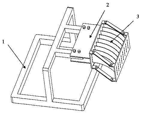
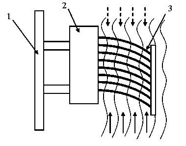
[0021] Specific implementation mode one: as figure 1 As shown, the present invention provides a piezoelectric power generation device under the impact of low-speed water flow, including a bracket 1 , a clamping structure 2 , and a composite piezoelectric bistable plate 3 .

[0022] In this embodiment, piezoelectric ceramic sheets are used as the piezoelectric material 4, and 10 piezoelectric ceramic sheets are pasted in the middle of the front of the composite piezoelectric bistable plate 3, such as Figure 4 As shown, the same number of piezoelectric ceramic sheets are also pasted on the same position on the reverse side of the composite piezoelectric bistable plate 3, and all piezoelectric ceramic sheets are connected in series by wires, and the composite piezoelectric bistable plate 3 is directly used as an electrode , and waterproof the entire composite piezoelectric bistable plate 3 with waterproof glue.

[0023] The number of composite piezoelectric bistable plates 3 de...

specific Embodiment approach 2

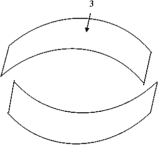
[0024] Embodiment 2: This embodiment provides a composite piezoelectric bistable plate, which is flat and rectangular before curing, and arc-shaped after curing. After curing, it has two stable shapes, such as image 3 As shown, the top is the first steady state, and the bottom is the second steady state. The composite piezoelectric bistable plate described in this embodiment adopts composite material and metal hybrid layering, solidifies at the curing temperature of the composite material, and can form an arc-shaped bistable effect due to residual thermal stress after cooling.

[0025] The layering is composed of symmetrical layering of composite materials and hybrid layering of metal composite materials, and both sides of the symmetrical layering of composite materials are hybrid layering layers of metal composite materials with symmetrical sizes.

[0026] Described composite material symmetrical layup is 90 ° and 0 ° composite material symmetrical layup, wherein 90 ° compos...

specific Embodiment approach 3

[0032] Specific implementation mode three: the specific layering method of the composite piezoelectric bistable plate in this implementation mode is as follows Figure 5 As shown, the upper part of the figure is the top view of the layup, and the lower part is the section view of the layup in different regions. The layup is divided into two regions, and the I region is a symmetrical layup of fiber composite materials, in which the 90° fiber composite material layer 5 is on the outside, and the 0° fiber composite material layer 6 is in the middle, such as [90 2 / 0 2 / 90 2 ]; the II area is the metal fiber mixed area, the same 90° fiber composite material layer 5 is on the outside, and the metal Al layer 7 is in the middle, such as [90 2 / Al / 90 2 ]. It should be noted that in order to keep the thickness consistent, the thickness of the 0° fiber composite layer in the I region should be the same as that of the metal Al in the II region, and the 90° fiber composite layer shoul...


PUM


Abstract

The invention discloses a piezoelectric generating set and method under low-speed water flow impacting. The piezoelectric generating set comprises a support, a clamping structure and a composite piezoelectric bi-stable state plate with pasted piezoelectric materials. The composite piezoelectric bi-stable state plate is clamped on the clamping structure and fixed to the support through the clamping structure. The piezoelectric generating method under low-speed water flow impacting through the piezoelectric generating set includes the steps that low-speed water flow is adopted for directly impacting the composite piezoelectric bi-stable state plate to drive the composite piezoelectric bi-stable state plate to be deformed between two stable states in a reciprocating mode along with the low-speed water flow, and then the piezoelectric materials are deformed to generate and collect electric energy. By means of the piezoelectric generating set and method, the function of converting low-speed wave energy into electric energy is achieved, and the piezoelectric generating set and method have the advantage of being simple in implementation structure and are convenient to use, high in practicability and capable of providing the electric energy for small low-power-consumption loads.

Description

Technical field [0001] The present invention is a technology field in renewable energy power generation, involving an energy collection device and method, and specially involves a device and method that can collect low -speed water wavy wavy methods. Background technique [0002] The problem of energy tensions in today's society is becoming more and more serious, making more and more people start paying attention to renewable environmental energy, such as wind energy, tidal energy, solar energy, wave energy, etc.Personal materials have good mechanical conversion characteristics, can realize the conversion of mechanical energy to electrical energy, and have a wide range of applications in the field of energy collection.CN103354434A revealed a dual -stabilized electrical cantilever vibration energy.CN103647475A provides a wide -frequency voltage vibration energy collection device.China's patent CN101951188 revealed a method and device that uses wind energy for wind energy.CN1030035...

Claims


Application Information

Patent Timeline
Patent Type & Authority Applications(China)
IPC IPC(8): H02N2/18
Inventor 戴福洪李昊潘殿坤
Owner HARBIN INST OF TECH
Why Eureka
Try Eureka