Biomass gasification furnace using furnace interlayer structure for decoking

A sandwich structure and biomass technology, applied in the manufacture of combustible gas, petroleum industry, etc., can solve the problems of energy loss contained in tar, high ash content of combustible gas, high tar content, etc., to reduce temperature, reduce tar content, and reduce pollution Effect

Inactive Publication Date: 2017-06-13
深圳市科陆绿能节能环保有限公司
View PDF8 Cites 0 Cited by
  • Summary
  • Abstract
  • Description
  • Claims
  • Application Information

AI Technical Summary

Problems solved by technology

However, since the natural direction of heat flow is from bottom to top, while the direction of gas discharge is from top to bottom, it takes a lot of power to extract combustible gas, and the combustible gas that comes out of the furnace contains more ash.
In addition, due to the high temperature of the gasification zone, the temperature of the combustible gas released from the furnace is relatively high, which needs to be cooled with water, and the heat resistance requirements of the gas extraction equipment are also high. Therefore, although the combustible gas tar released from the furnace The content is low, but there are some difficulties in getting gas
[0008] All in all, the existing updraft and downdraft gasifiers have their own advantages and disadvantages, and further improvement is still needed, especially the high tar content of the updraft gasifier, which not only causes the loss of energy contained in the tar, but also directly Discharge will cause serious environmental pollution

Method used


Image

  • Biomass gasification furnace using furnace interlayer structure for decoking
  • Biomass gasification furnace using furnace interlayer structure for decoking
  • Biomass gasification furnace using furnace interlayer structure for decoking

Examples


Embodiment 1

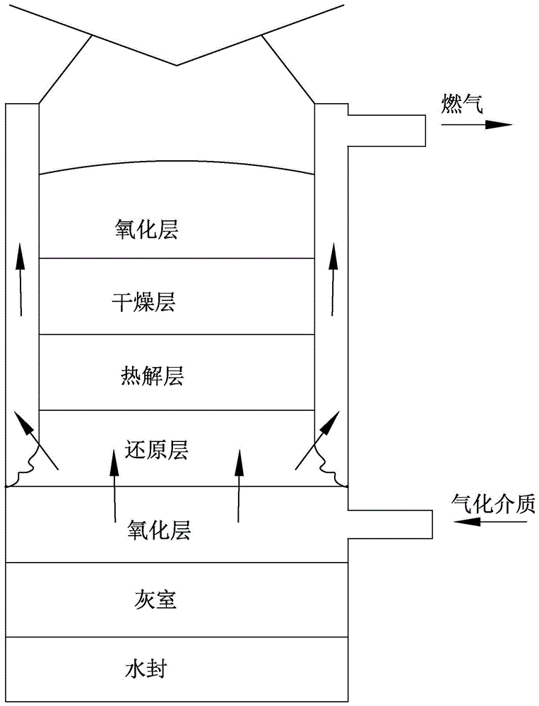
[0045] Such as Figure 4 As shown, the furnace body 10 includes a first furnace body 101 and a second furnace body 102 . The lower end of the first furnace body 101 is open, the upper end of the second furnace body 102 is open, and the radius or cross-sectional size of the second furnace body 102 is larger than that of the first furnace body 101 . The second furnace body 102 is sleeved in the middle or middle lower part of the first furnace body 101 , and its interiors are interconnected, and the side walls are spaced apart, thereby forming a sandwich structure with gas passages 15 . The first furnace body 101 and the second furnace body 102 can be integrally formed, or separate parts can be sealed and connected into one body by a known method. The feeding port 11 is provided on the top of the first furnace body 101 . The fire grate 14 is arranged in the second furnace body 102 , which can be a known automatic fire grate 14 . The drying layer and the pyrolysis layer are arr...

Embodiment 2

[0048] Such as Figure 5 As shown, the furnace body 10 of this embodiment includes a first furnace body 101 , a second furnace body 102 , and a third furnace body 103 , which are internally connected to each other. The lower end of the first furnace body 101 is open, and the upper and lower ends of the second furnace body 102 are open, and the second furnace body 102 is sheathed in the middle or lower part of the first furnace body 101 . The upper end of the third furnace body 103 is open, and it is sheathed in the middle or lower part of the second furnace body 102 . The first furnace body 101, the second furnace body 102, and the third furnace body 103 are nested in sequence to form a sandwich structure with gasification channels, wherein a gasification gas is formed between the side walls of the first furnace body 101 and the second furnace body 102. The gasification medium channel 16, through which the gasification medium passes into the oxide layer. A gas channel 15 is ...

Embodiment 3

[0050] Such as Image 6 As shown, the furnace body 10 of this embodiment includes a first furnace body 101 and a second furnace body 102 . The first furnace body 101 is a hermetic furnace body 10, which is divided into a drying layer, a pyrolysis layer, a reduction layer and an oxidation layer from top to bottom. The second furnace body 102 is the furnace body 10 with upper and lower ends open, which is arranged in the first furnace body 101 , its lower end opening is located in the reducing layer, and its upper end opening is connected with the gas outlet 13 through the communication pipe 17 . The gas outlet 13 can be arranged on the side wall of the first furnace body 101 at any height. The fire grate 14 is arranged in the first furnace body 101 and is located under the oxide layer. The feeding port 11 is arranged on the top of the first furnace body 101 , and the gasification medium inlet 12 is arranged under the fire grate 14 , which feeds the gasification medium into th...


PUM


Abstract

A biomass gasification furnace that utilizes the interlayer structure of the furnace body for decoking, which includes a furnace body provided with a drying layer, a pyrolysis layer, a reduction layer and an oxidation layer, and the furnace body is provided with a feeding port, a gasification medium inlet and a The gas outlet is provided with a fire grate in the furnace body, which is characterized in that the furnace body is constructed as a sandwich structure with a gasification channel, and the gasification channel includes a gas channel and a gasification medium channel, wherein one end of the gas channel communicates with the reducing layer, and the other One end is connected with the gas outlet, so that the combustible gas generated in the furnace is forced to flow through the reducing layer and discharged, and the high temperature of the reducing layer is used to further crack the tar in the combustible gas to reduce the tar content. The invention overcomes the shortcomings of traditional gasifiers and effectively combines its advantages, solving the problems of high tar content of combustible gas discharged from the updraft gasifier and inconvenient addition of materials, and difficulty in gas extraction of the downdraft gasifier question. In addition, the present invention uses the structure of the furnace body to construct channels, which can increase the flow rate of air intake / exit, which is beneficial to maintain the stability of the reaction in the furnace.

Description

[0001] 【Technical field】 [0002] The invention relates to a biomass gasification furnace, in particular to a biomass gasification furnace which utilizes a furnace interlayer structure for decoking. [0003] 【Background technique】 [0004] Biomass gasification is the process of producing combustible gas through dry distillation and thermochemical reaction of biomass under anaerobic conditions. Common biomass gasification processes include processes or reactions such as drying, pyrolysis (also known as cracking), oxidation, and reduction. Biomass gasification is usually carried out in a biomass gasifier. Therefore, the internal structure of a biomass gasifier can be divided into a drying layer (also known as a drying area), a pyrolysis layer (area), and an oxidation layer (area) according to the gasification reaction process. Layer (area), reduction layer (area). After the biomass raw material enters the gasifier, it is heated in the drying layer to evaporate the water in the ...

Claims


Application Information

Patent Timeline
Patent Type & Authority Patents(China)
IPC IPC(8): C10J3/20C10J3/84
Inventor 邱云原
Owner 深圳市科陆绿能节能环保有限公司
Why Eureka
Try Eureka