
Long-focus tight-focusing surface plasmonic lens under radially polarized beam

A surface plasmon and radially polarized light technology, applied in the field of nanophotonics, can solve the problems of limited application range and achieve the effects of compact structure, compressed focal spot, and good application prospects

Active Publication Date: 2014-10-08
NANJING UNIV OF POSTS & TELECOMM
View PDF8 Cites 25 Cited by
  • Summary
  • Abstract
  • Description
  • Claims
  • Application Information

AI Technical Summary

Problems solved by technology

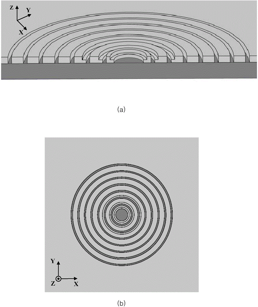
Due to the particularity of the radially polarized light field distribution, Spps can be excited from all directions, while increasing the number of slits to increase the irradiation area and improve the excitation efficiency, such as the PL lens proposed by Chen W et al. (Chen W, Abeysinghe D C, Nelson R L, et al.Plasmonic lens made of multiple concentric metallic rings under radially polarized illumination[J].Nano letters,2009,9(12):4320-4325.), the incident light is excited in the M-I-M structure formed by the concentric slit Spps, and spread on the lens surface, forming an extremum at the lens center, but because its intensity is mainly concentrated on the lens surface, its application range is also greatly limited

Method used


Image

  • Long-focus tight-focusing surface plasmonic lens under radially polarized beam
  • Long-focus tight-focusing surface plasmonic lens under radially polarized beam
  • Long-focus tight-focusing surface plasmonic lens under radially polarized beam

Examples


Embodiment Construction

[0017] Embodiments of the present invention will be described in detail below in conjunction with the accompanying drawings.

[0018] Specific calculation process 1: Bessel-Gaussian vector beam expression

[0019] For a monochromatic vector beam propagating along the Z direction in free space, its electric field vector E can be written in cylindrical coordinates as:

[0020]

[0021] where F is the vector amplitude of the electric field, r and is the cylindrical coordinate, k=ω / c is the angular frequency of the monochromatic light, and c is the speed of light in vacuum. The electric field vector of this beam is established under the vector Helmholtz norm, satisfying:

[0022] ▿ × ▿ × E - k 2 E = 0 - - - ( 1.2 )

[0023] Since the longitudinal electric field com...


PUM


Abstract

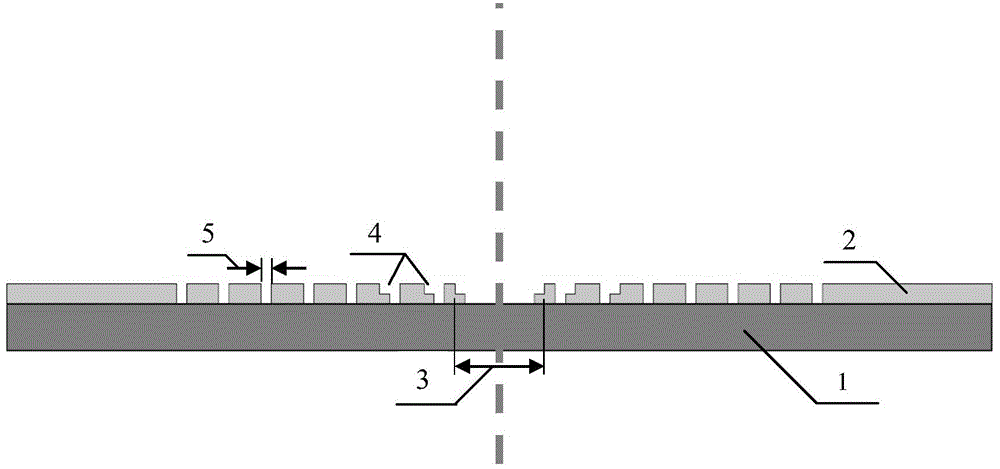
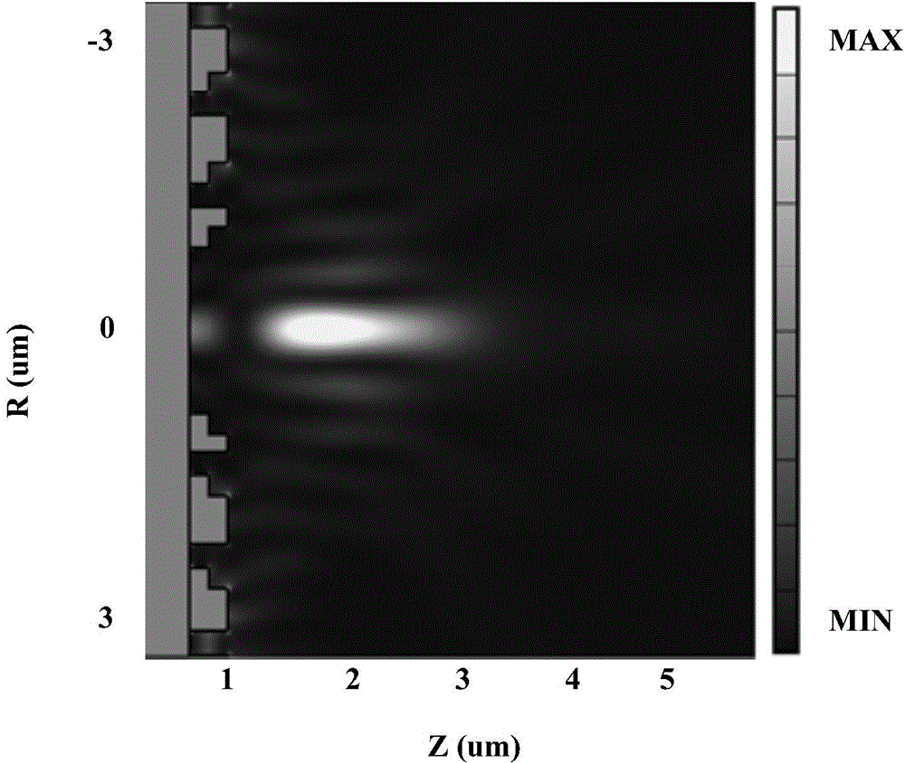
The invention discloses a long-focus tight-focusing surface plasmonic lens under a radially polarized beam. The surface plasmonic lens comprises a dielectric substrate and a metal thin film located on the dielectric substrate. A T-type micropore is etched in the center of the metal thin film. A periodical concentric ring structure is distributed on the periphery of the micropore. The periodical concentric ring structure comprises concentric ring grooves with the phase modulation function and peripheral concentric ring grooves. The radially polarized beam enters the surface plasmonic lens from the bottom, passes a metal-dielectric-metal type waveguide structure and effectively excites Spps in all directions; while the T-type micropore in the center enhances the intensity of the transmitted beam, tight focusing is formed by center hole transmission light and the Spps scattered to free space due to multiple-mode interference, phase positions of outlets of the stepped concentric ring grooves are regulated, a focal spot can be further compressed in cooperation with the antenna effect through multi-beam interference, the light intensity of a focal point is enhanced, the focusing characteristic of the lens is improved, and long-focus sub-wavelength tight focusing under the excitation of the radially polarized beam is realized.

Description

technical field [0001] The invention relates to the field of nanophotonics, in particular to a long-focus, tightly-focused surface plasmon lens excited by radially polarized light. Background technique [0002] Surface plasmon polaritons (Surface Plasmon Polaritons, SPPs) is an electromagnetic wave mode localized on the metal surface, which is an electromagnetic oscillation that excites and couples the fluctuation of charge density by the interaction between light and free electrons on the metal surface at the metal-dielectric interface. With the characteristics of near-field enhancement, surface confinement, and short wavelength, it plays an important role in the research of nanophotonics. Various nanophotonic devices based on SPPs are considered to be the most promising basis for the realization of nanoscale all-optical integrated circuits. Due to the short-wavelength characteristics and strong surface binding of Spps, it can be focused into a tightly focused spot that br...

Claims


Application Information

Patent Timeline
Patent Type & Authority Applications(China)
IPC IPC(8): G02B6/122B82Y20/00
Inventor 陆云清呼斯楞陆懿许吉王瑾
Owner NANJING UNIV OF POSTS & TELECOMM
Learn More