
Multifunctional ion gun

An ion gun, multi-functional technology, applied in the direction of discharge tube ion gun, discharge tube, electrical components, etc., can solve the problems of difficult disassembly, narrow ion energy range, unadjustable beam spot size, etc., to ensure collimation, structure, etc. Compact, effect that compensates for machining inconsistencies

Active Publication Date: 2014-10-08
LANZHOU UNIVERSITY
View PDF10 Cites 4 Cited by
  • Summary
  • Abstract
  • Description
  • Claims
  • Application Information

AI Technical Summary

Problems solved by technology

There are defects such as complex ion source structure, difficult disassembly, and difficult maintenance
The cold cathode ion source mainly adopts the principle of Penning discharge, and its structure is relatively simple, but it requires high voltage power supply, and the generated ion beam current is unstable.
Generally speaking, the ion energy range of existing ion guns is narrow, the ion transmission distance is generally less than 100mm, the beam collimation is poor, and the beam spot size cannot be adjusted, which limits its application range

Method used


Image

  • Multifunctional ion gun
  • Multifunctional ion gun
  • Multifunctional ion gun

Examples


Embodiment Construction

[0031] The preferred embodiments of the present invention will be described below in conjunction with the accompanying drawings. It should be understood that the preferred embodiments described here are only used to illustrate and explain the present invention, and are not intended to limit the present invention.

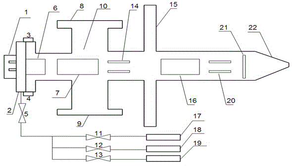
[0032] Such as figure 1 As shown, a multifunctional ion gun includes an ionization chamber 6, a first lens 7, a second lens 16, a first deflector 14, a second deflector 20, a slit 21, a four-way flange 10, and a transition flange 15 and a tapered cylinder 22, the ionization chamber 6, the first lens 7 and the first deflection plate 14 are located in the pipeline of the four-way flange 10, and the first lens 7 is located between the ionization chamber 6 and the first deflection plate 14, The first deflector plate 14 is installed at the near end of the transition flange 15, the ionization chamber 6 is installed at the far end of the transition flange 15, the second le...


PUM


Abstract

The invention discloses a multifunctional ion gun which comprises an ionization chamber, a first lens, a second lens, a first deflecting plate, a second deflecting plate, a slot, a four-way flange, a transition flange and a cone-shaped cylinder. The ionization chamber, the first lens and first deflecting plate are placed in a pipeline of the four-way flange. The first lens is placed between the ionization chamber and the first deflecting plate. The first deflecting plate is placed at the near end of the transition flange. The ionization chamber is arranged at the far end of the transition flange. The second lens, the second deflecting plate and the slot are placed in the cone-shaped cylinder. The second deflecting plate is placed between the second lens and the slot. The second lens is arranged at the near end of the transition flange. The slot is formed in the far end of the transition flange. The four-way flange and the cone-shaped cylinder are connected through the transition flange. The purposes that the structure is compact, functions are various, performance is stable, and ion beam transmission distance is enhanced are achieved.

Description

technical field [0001] The invention relates to the fields of surface science application technology, ultra-high vacuum technology and ion beam technology, in particular to a multifunctional ion gun. Background technique [0002] In the field of surface science, the cleanliness of the sample surface has a crucial influence on the experiment. Argon ion sputtering is currently a standard method for cleaning surfaces in situ. [0003] In basic research, such as low energy ion-scattering spectroscopy, it is necessary to use low energy ion beams as probes to study surface composition. In the application of time-of-flight mass spectrometry, a pulsed ion beam is required. In the field of microfabrication, it is often necessary to use low-energy high-current ion beams to sputter samples to implement layer-by-layer peeling. [0004] All of the above experimental studies have put forward strict technical requirements for ion beams, but the existing ion guns cannot meet many experim...

Claims


Application Information

Patent Timeline
IPC IPC(8): H01J3/04H01J37/08
Inventor 陈林陈熙萌郭艳玲丁斌
Owner LANZHOU UNIVERSITY
Learn More