
Method for regulating and controlling microstructure of oxide electrode in working period of fuel cell

A fuel cell and microscopic morphology technology, applied in the direction of fuel cell control, battery electrodes, fuel cell additives, etc., can solve problems such as unfavorable electrode reaction process, waste of material and manpower, particle agglomeration, etc.

Inactive Publication Date: 2014-10-08
HARBIN INST OF TECH
View PDF6 Cites 6 Cited by
  • Summary
  • Abstract
  • Description
  • Claims
  • Application Information

AI Technical Summary

Problems solved by technology

[0003] The purpose of the present invention is to solve the problem that the current methods for regulating the microstructure of oxide electrodes are all carried out in the electrode preparation process, and the electrodes need to be sintered at high temperature, so that the particles are agglomerated, resulting in a decrease in the effective reaction area and internal porosity of the electrode. It is not conducive to the reaction process of the electrode, which greatly wastes material and manpower and also increases the technical problem of preparation cost, thus providing a method for regulating the microscopic morphology of the oxide electrode during the operation of the fuel cell

Method used

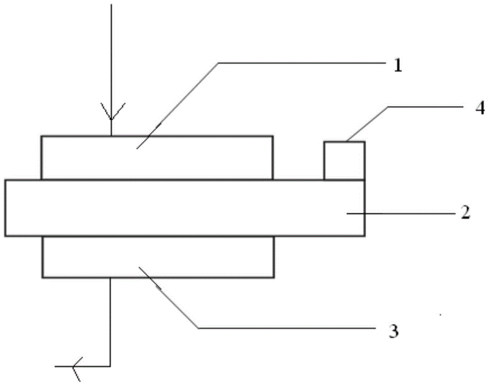
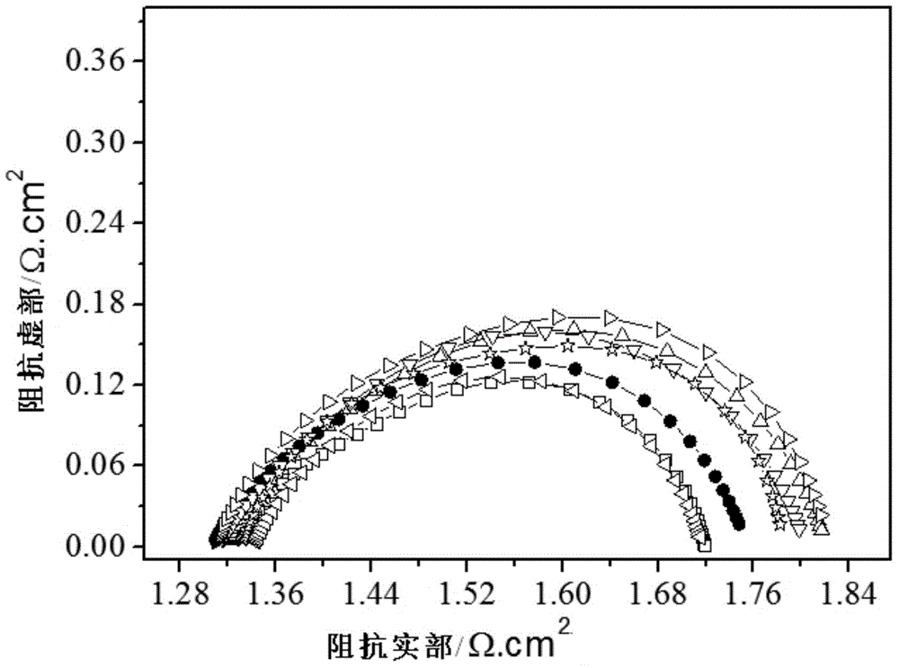
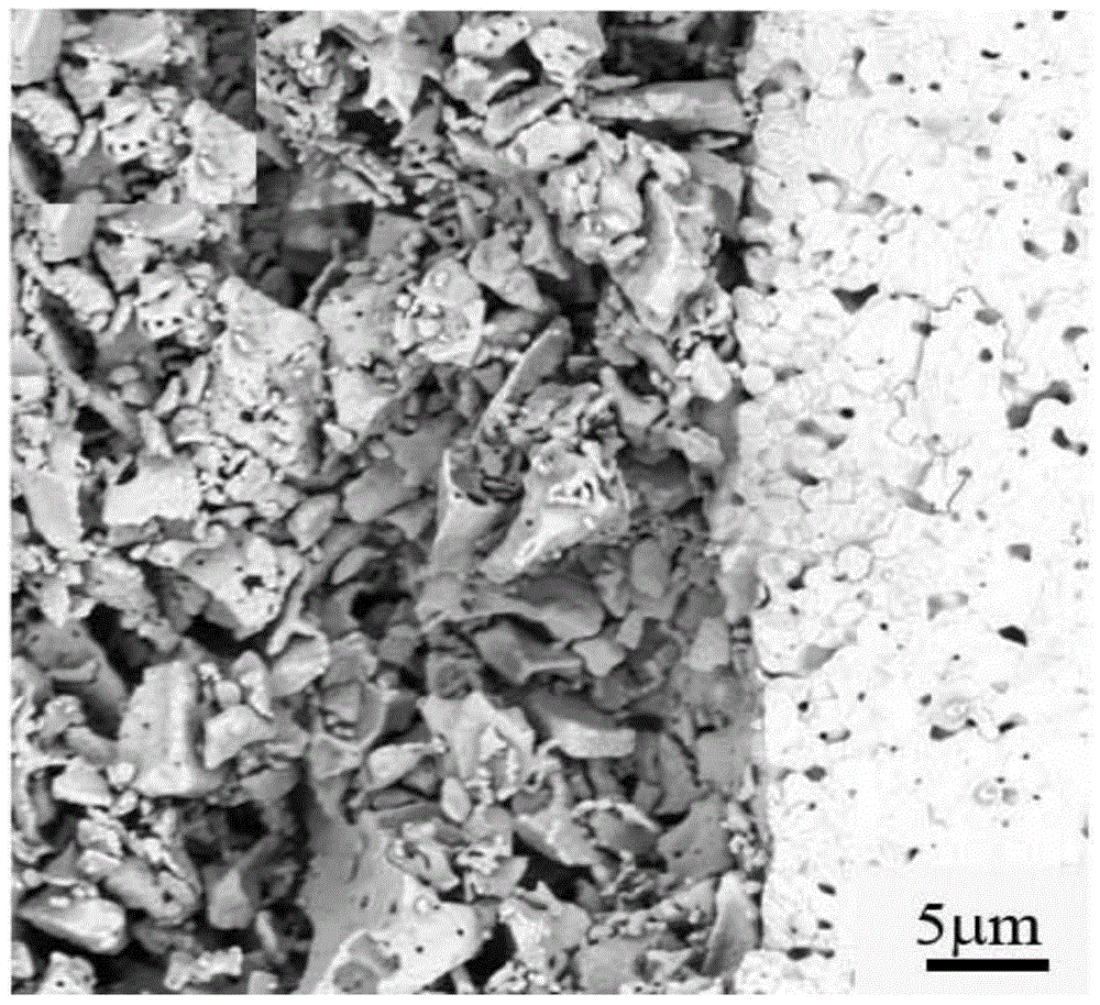

Image

  • Method for regulating and controlling microstructure of oxide electrode in working period of fuel cell
  • Method for regulating and controlling microstructure of oxide electrode in working period of fuel cell
  • Method for regulating and controlling microstructure of oxide electrode in working period of fuel cell

Examples


specific Embodiment approach 1

[0013] Specific implementation mode 1: This implementation mode is a method for regulating the microscopic morphology of oxide electrodes during the operation of the fuel cell, which is specifically carried out according to the following steps:

[0014] 1. Coating the conductive silver paste to the oxide working electrode of the fuel cell, the reference electrode of the fuel cell and the counter electrode of the fuel cell, and then coating the oxide working electrode of the fuel cell, the reference electrode of the fuel cell and the fuel Lead out a wire from the conductive silver paste on the counter electrode of the battery, put it into a muffle furnace and dry it for 5min to 10min at a temperature of 80°C to 200°C, and connect the three wires drawn out from the conductive silver paste Connect to the corresponding terminal of the electrochemical workstation, and then increase the temperature in the muffle furnace from 80°C to 200°C to 400°C to 1000°C within 0.5h to 2.5h, and t...

specific Embodiment approach 2

[0019] Specific embodiment 2: The difference between this embodiment and specific embodiment 1 is that the oxide working electrode of the fuel cell described in step 1 has ABO 3 Perovskite structure oxides of general formula or with A 2 BO 4 A perovskite-like structure oxide of the general formula. Others are the same as in the first embodiment.

specific Embodiment approach 3

[0020] Specific embodiment three: the difference between this embodiment and specific embodiment two is: the chemical formula of the perovskite structure oxide with ABO3 general formula described in step one is CDO 3 、CD 1-x E. x o 3 、C 1-x f x do 3 or C 1-x f x D. 1-y E. y o 3 ; where CD 1-x E. x o 3 、CDO 3 、C 1-x f x do 3 and C 1-x f x D. 1-y E. y o 3C is a rare earth element, C is specifically La, Ce, Pr, Nd, Sm, Eu, Gd, Tb, Dy, Ho, Er, Tm, Yb, Lu or Y, F is an alkaline earth element, and F is specifically Ca, Sr Or Ba, D is a 3d transition group metal element, D is specifically Ti, V, Cr, Mn, Fe, Co, Ni or Cu, E is a 3d transition group metal element, and E is specifically Ti, V, Cr, Mn, Fe , Co, Ni or Cu, O is oxygen element; CD 1-x E. x o 3 Medium 01-x f x do 3 Medium 01-x f x D. 1-y E. y o 3 In 0<x<1, 0<y<1. Others are the same as in the second embodiment.


PUM


Abstract

The invention provides a method for regulating and controlling the microstructure of an oxide electrode in the working period of a fuel cell, and relates to a method for regulating and controlling the microstructure of the oxide electrode. The method aims at solving the technical problems that material and manpower resources are greatly wasted and the preparation cost is increased due to the reduction of the effective reaction area and the internal porosity of the electrode as well as bad influence on the reaction process of the electrode caused by particle aggregation as the existing methods for regulating and controlling the microstructure of the oxide electrode are all implemented in the preparation process of the electrodes and each electrode needs to be sintered at high temperature. The method comprises the steps of firstly, connecting the fuel cell with an electrochemical workstation and heating, and secondly, performing anodic polarization treatment on the working electrode at high temperature, and cooling to room temperature. The method is mainly applied to control of the microstructure of the oxide electrode of the fuel cell.

Description

technical field [0001] The invention relates to a method for regulating the microscopic appearance of an oxide electrode. Background technique [0002] At present, the methods of preparing electrodes mainly adopt dry pressing method, screen printing co-sintering method and coating method. The dry pressing method is simple to operate, but the powder distribution is not easy to control, and it is easy to stratify. Screen printing technology is low-cost, but film formation is easily affected by parameters such as powder properties (particle size and shape) and rheological properties of slurry. The coating method has the characteristics of low equipment cost, thin film formation, and simple process, but because it needs to go through the slurry coating on the substrate surface-drying-pre-sintering-sintering process, the entire process is tedious and tedious, which greatly reduces the cost. membrane efficiency. However, no matter which method is used, there will be agglomerati...

Claims


Application Information

Patent Timeline
Patent Type & Authority Applications(China)
IPC IPC(8): H01M8/04H01M8/04298
CPCY02E60/50H01M4/8875
Inventor 毋妍妍黄喜强吕喆张耀辉魏波朱星宝王志红郭朋真李鹏章
Owner HARBIN INST OF TECH
Learn More