
Balance feed differential slot antenna for restraining common-mode noise

A technology that balances feeding and suppresses common mode. It is applied to slot antennas, antennas, antenna coupling and other directions. It can solve the problems of increasing volume and reducing the common mode rejection ratio of post-stage circuits, and achieve low loss, avoid loss and volume. Increased, high-efficiency effects

Active Publication Date: 2014-10-08
SOUTHEAST UNIV
View PDF5 Cites 142 Cited by
  • Summary
  • Abstract
  • Description
  • Claims
  • Application Information

AI Technical Summary

Problems solved by technology

[0005] Purpose of the invention: In order to overcome the deficiencies in the prior art, the present invention provides a balanced feed differential slot antenna that suppresses common-mode noise. The differential-mode excitation gain is much greater than the common-mode excitation gain. In the case of different antenna radiation patterns and reflection coefficients, it is possible to effectively suppress the common-mode noise part of the transmitted electromagnetic wave, reduce the common-mode noise signal input to the subsequent differential circuit, and reduce the common-mode rejection ratio ( CMRR) requirements, while avoiding the loss and volume increase caused by the balun (when the single-ended circuit is connected to the double-ended differential circuit, it is necessary to use the balun to convert the single-ended signal into a double-ended differential signal for connection; use a differential antenna Connection with differential circuit can save Balun), has the advantages of miniaturization, planarization, can be realized through a dielectric substrate, and is easy to integrate with the subsequent RF circuit

Method used


Image

  • Balance feed differential slot antenna for restraining common-mode noise
  • Balance feed differential slot antenna for restraining common-mode noise
  • Balance feed differential slot antenna for restraining common-mode noise

Examples


Embodiment Construction

[0021] The present invention will be further described below in conjunction with the accompanying drawings.

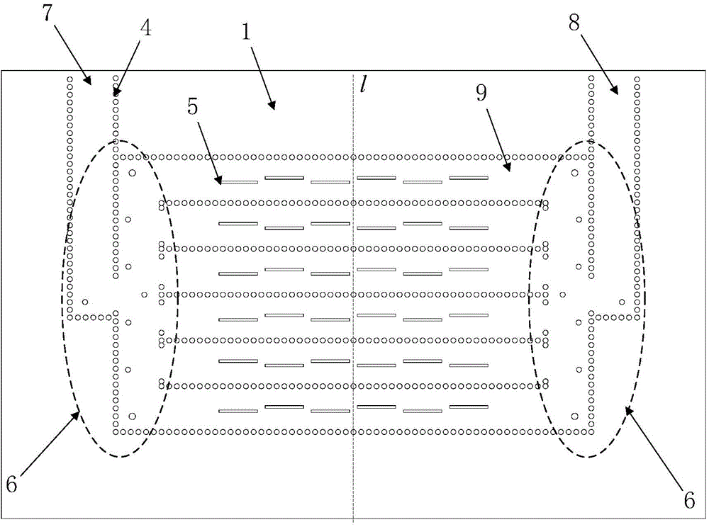
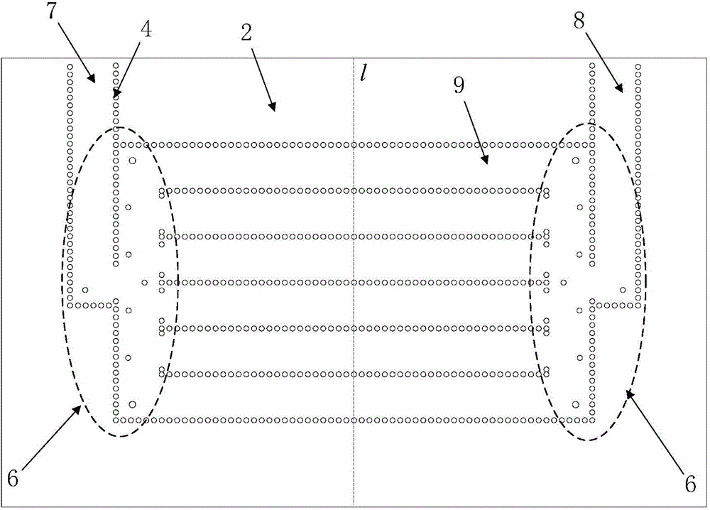
[0022] A balanced feed differential slot antenna for suppressing common mode noise, comprising a dielectric substrate 3, a top metal layer 1 disposed on the upper surface of the dielectric substrate 3, a bottom metal layer 2 disposed on the lower surface of the dielectric substrate 3, and on the dielectric substrate 3 Metallized through holes 4 are provided, and the upper and lower ends of the metallized through holes 4 are respectively connected to the top metal layer 1 and the bottom metal layer 2, and the top metal layer 1, the bottom metal layer 2 and the metallized through holes 4 jointly realize n base On-chip integrated waveguide structure 9, differential signals are excited at both ends of each substrate integrated waveguide structure 9 to form a differential pair-fed substrate integrated waveguide; for any one substrate integrated waveguide structure 9, a group...


PUM


Abstract

The invention discloses a balance feed differential slot antenna for restraining common-mode noise. Based on a planar substrate integrated waveguide structure, the slot antenna is adopted as a radiating unit; due to different electric field distributions in the substrate integrated waveguide under different stimulation modes, energy can be effectively radiated under the different-mode signal stimulation, and most of energy is reflected under the common-mode signal stimulation. Due to the adoption of the antenna of the structure, different-mode signals can be effectively transmitted and received, meanwhile, common-mode signals are restrained from being transmitted and received, and therefore the function of restraining common-mode noise is achieved.

Description

technical field [0001] The invention relates to a balanced feed differential slot antenna capable of suppressing common-mode noise, planar integration and miniaturization, which belongs to the communication system design technology. Background technique [0002] As an important part of modern wireless communication systems, microwave and millimeter wave antennas have the basic characteristic of converting electrical signals into electromagnetic wave signals or converting electromagnetic wave signals into electrical signals. According to the system structure of the transceiver, the antenna is located at the final stage of the system and is responsible for transmitting radio frequency signals or receiving electromagnetic wave signals. The antenna directly affects the performance of the entire system. Choosing the right antenna can significantly improve the overall system performance. [0003] With the development of communication technology, microwave and millimeter wave tec...

Claims


Application Information

Patent Timeline
IPC IPC(8): H01Q25/04H01Q13/10H01Q1/52
Inventor 洪伟杨天杨张彦
Owner SOUTHEAST UNIV
Learn More