
Automatic electricity generation energy storage device

An energy storage device and self-generating technology, applied in circuit devices, battery circuit devices, generators/motors, etc., can solve problems such as being unable to meet or adapt to specific working environments and requirements, and it is difficult for autonomous microsystems to provide energy.

Inactive Publication Date: 2014-10-08
YANGZHOU UNIV
View PDF7 Cites 13 Cited by
  • Summary
  • Abstract
  • Description
  • Claims
  • Application Information

AI Technical Summary

Problems solved by technology

In the near future, due to the development of micro-nano systems and their real-time monitoring of human health in situ, infrastructure monitoring, environmental monitoring, Internet of Things and military technology applications, the traditional method of using batteries to provide power will become possible It cannot meet or adapt to the specific working environment and requirements. The MEMS in the existing technology has the characteristics of miniaturization, mass production, integration and interdisciplinary, and has concentrated many cutting-edge achievements in the development of science and technology today.
Traditional energy supply devices are gradually unable to meet the needs of technological development, and it is difficult to provide energy for various miniature portable microsystem devices or autonomous microsystems

Method used


Image

  • Automatic electricity generation energy storage device
  • Automatic electricity generation energy storage device
  • Automatic electricity generation energy storage device

Examples


Embodiment Construction

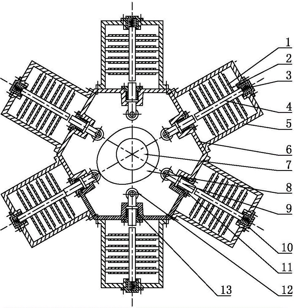
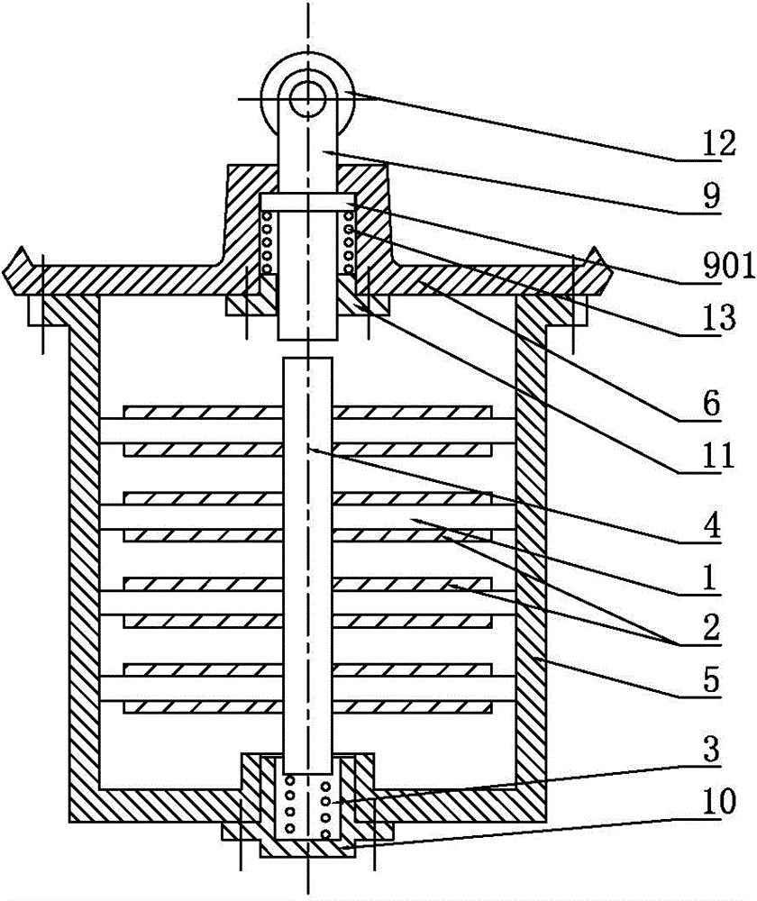
[0015] Such as Figure 1-3 As shown, it is a self-generating energy storage device. A rotating shaft 7 is arranged in the housing 6, and a cam 8 is installed on the rotating shaft 7. The rotating shaft 7 can be driven to rotate by manpower, wind power, etc.; At least one group of power generation units is arranged around, preferably four or six groups, and there are six groups in this embodiment. The power generation unit includes a frame 5, and a plurality of elastic cantilever plates 1 are arranged in parallel in the frame 5. The elastic cantilever plates 1 are made of metal materials, and the center of the elastic cantilever plate 1 is connected with the mass block 4, and the mass block 4 is cylindrical or rhombic; The surface of the elastic cantilever plate 1 is pasted with a piezoelectric sheet 2, and the piezoelectric sheet 2 is electrically connected to the electric energy storage device; one end of the mass block 4 is elastically supported in the frame 5 by the oscilla...


PUM


Abstract

The invention discloses an automatic electricity generation energy storage device, and belongs to the field of electricity generation devices. The automatic electricity generation energy storage device comprises a shell. A rotating shaft is arranged inside the shell. A cam is installed on the rotating shaft. At least one set of electricity generation unit is arranged at the portion, on the periphery of the cam, of the shell. Each electricity generation unit comprises a frame, wherein a plurality of elastic cantilever slabs are arranged inside the frame in parallel, the center of each elastic cantilever slab is connected with a mass block, piezoelectric patches are stuck to the surface of the elastic cantilever slabs, and the piezoelectric patches are electrically connected with an electric energy storage device body; one end of each mass block is elastically supported into the corresponding frame, the other end of each mass block is correspondingly provided with an ejector rod, the ejector rods are arranged inside guiding pieces in a matched mode, and the guiding pieces are fixedly connected with the shell; according to the positions of the ejector rods, the ejector rods make contact with and press the mass blocks in a clearance mode when the cam rotates. When the cam rotates, the mass blocks can elastically vibrate, the piezoelectric patches generate the automatic electricity generation effect, the vibration mechanical energy is converted into electric energy to be stored, and the automatic electricity generation energy storage device can be used as a power source of a small-power electricity consumption device.

Description

technical field [0001] The invention relates to a power generating device, in particular to a small power generating device. Background technique [0002] At present, traditional energy research and development can be mainly divided into five aspects: generation and conversion of large-scale energy; development of sustainable green energy; efficient transmission of electric power and smart grid; high-density storage of electric energy; effective energy-saving technology and energy recovery . Most of our demand for electric energy is concentrated in industrial electricity, transportation, construction, home and office energy. These energy needs can be met by a large-scale electrical grid. However, since the popularization of personal mobile electronic products such as laptops and mobile phones, it is particularly important to solve small-scale power consumption, which mainly relies on batteries at present. In the near future, due to the development of micro-nano systems an...

Claims


Application Information

Patent Timeline
IPC IPC(8): H02N2/18H02J7/00
Inventor 曾励张小红王军领徐大明
Owner YANGZHOU UNIV
Learn More