
Touch key signal detection method and circuit based on mutual capacitance

A technology of signal detection and mutual capacitance, which is applied in the direction of electrical components, electronic switches, pulse technology, etc., can solve the problems of increasing system dynamic power consumption, low detection speed, signal false detection, etc., and achieve system power saving and flexible working frequency , the effect of low dynamic power consumption

Active Publication Date: 2014-10-08
DONGGUAN LESHENG ELECTRONICS
View PDF5 Cites 9 Cited by
  • Summary
  • Abstract
  • Description
  • Claims
  • Application Information

AI Technical Summary

Problems solved by technology

[0005] (1) The detection speed is low; "relaxation oscillation" detects touch signals by detecting frequency changes. The detection circuit needs to pass several clock cycles to determine the change in frequency, and single-cycle touch signal detection cannot be realized.
[0006] (2) High power consumption; because it takes several clock cycles to detect the touch signal, the self-capacitance of the touch button is repeatedly charged and discharged, which increases the dynamic power consumption of the system
[0007] (3) It is difficult to realize the low-power standby mode; after "sleep", the general system will reduce the dynamic power consumption by reducing the operating frequency, and if the touch key of the "relaxation oscillation" method changes the frequency, it will cause signal misdetection, Therefore, in the standby mode and the working mode, the power consumption is almost the same, which cannot meet the long standby time requirement under the condition of battery power supply.

Method used


Image

  • Touch key signal detection method and circuit based on mutual capacitance
  • Touch key signal detection method and circuit based on mutual capacitance
  • Touch key signal detection method and circuit based on mutual capacitance

Examples


Embodiment Construction

[0035] Embodiments of the present invention will now be described with reference to the drawings, in which like reference numerals represent like elements.

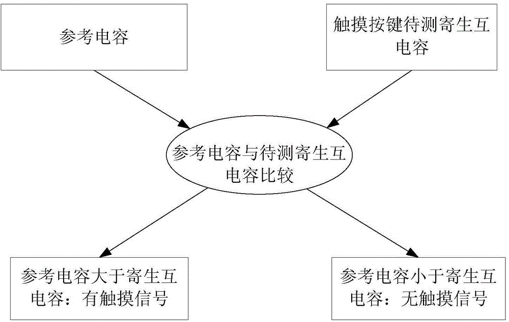
[0036] For a better understanding of the present invention, please refer to figure 2 To describe the working principle of the present invention as follows:

[0037] In the present invention, a reference capacitor is firstly set as a reference object for mutual capacitance touch key signal detection; when measuring, the parasitic mutual capacitance of the touch key is compared with the reference capacitance (reference object), and if the mutual capacitance of the touch key is smaller than the reference capacitance value, then A touch signal is detected, otherwise it means no touch signal is detected.

[0038] Specifically, using the principle of charge conservation and the method of charge transmission, by complementary driving the reference capacitance and the mutual capacitance of the touch button, the stored charge in...


PUM


Abstract

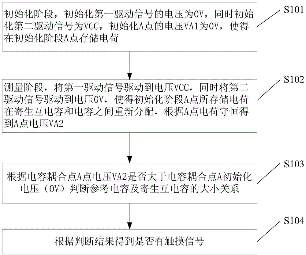
The invention discloses a mutual capacitance type touch key signal detection method. The method comprises the steps that initialization is carried out, wherein the electric charge quantity of an A point in the initialization phase is obtained; measurement is carried out, the voltage of the A point is obtained according to conservation of the electric charge of the A point; whether reference capacitance is larger than parasitic mutual capacitance or not is judged according to the judgment result of whether the voltage VA2 of a capacitive coupling point A is larger than the initial voltage of the capacitive coupling point A or not; whether a touch signal exists or not is judged according to the judgment result. Compared with the prior art, detection of the touch signal is completed within one period through a reference capacitance comparison method, the detection speed is much higher than that of a traditional relaxation oscillation method; Because of the single-period detection, a capacitor of a touch key does not need to be charged and discharged frequently, system power consumption is greatly saved; in addition, due to the method, a system has very low dynamic power consumption, working frequency can be flexibly changed, the touch key can be used under the low-power-consumption standby mode with the rigorous requirement for power consumption, and the hardware guarantee is provided for a full-touch human-computer interaction interface. The invention further discloses a detection circuit of the touch key signal detection method.

Description

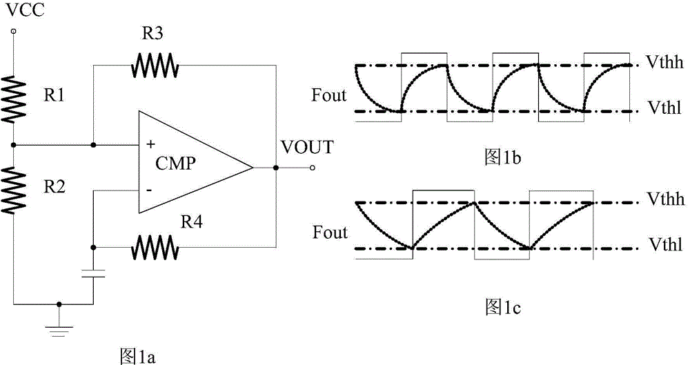
technical field [0001] The present invention relates to the technical field of touch key signal detection, and more particularly relates to a mutual capacitance-based touch key signal detection method and a detection circuit thereof. Background technique [0002] The traditional touch button signal detection method is generally realized by the "relaxation oscillation" method based on self-capacitance. The basic principle of "relaxation oscillation" touch detection is a relaxation oscillator that is continuously charged and discharged. Without touching the switch, the relaxation oscillator has a fixed charge and discharge cycle, and the frequency is measurable. If you touch the switch with a finger or a stylus, the dielectric constant of the capacitor will increase, the charging and discharging cycle will become longer, and the frequency will decrease accordingly. Therefore, the change of the measuring cycle can detect the touch action. [0003] Please refer to Figure 1a ,...

Claims


Application Information

Patent Timeline
IPC IPC(8): H03K17/975
Inventor 汪玉龙李博
Owner DONGGUAN LESHENG ELECTRONICS
Learn More