
Selective electrode type solar cell grid line printing position precision detecting method

A solar cell and printing position technology, which is applied to the general parts of printing machinery, printing, printing machines, etc., can solve the problems of harsh environmental requirements, light pollution, and the inability to detect the coincidence accuracy of the printing area of ​​metal grid lines and heavy diffusion grid lines, etc., to achieve The effect of reducing production costs and simplifying the process

Inactive Publication Date: 2014-10-15
SHENBEN ELECTRICAL TECH SHANGHAI
View PDF0 Cites 11 Cited by
  • Summary
  • Abstract
  • Description
  • Claims
  • Application Information

AI Technical Summary

Problems solved by technology

[0012] However, conventional optical detection methods cannot detect the coincidence accuracy of the actual printing position of the metal grid lines and the printed area of ​​the heavily diffused grid lines after the grid lines are printed using pattern positioning technology
This is not only because the anti-reflection film reduces the recognizability between the re-expansion area and the low-expansion area, but also because the reflection ability of the metal grid line to the detection light source is much higher than the reflection ability of the cell surface to light , the reflected light of the metal grid line will bring light pollution to the surrounding area of ​​the metal grid line, making it impossible to visually recognize the position of the re-expansion area
[0013] Although photoluminescence technology has no incident light source in the image acquisition process, it can avoid the problem of light pollution caused by the reflection of metal grid lines, but due to the limitation of photoluminescence efficiency, the interference of anti-reflection film and lattice, heavy diffusion grid line printing Region identification is not reliable
At the same time, because the photoluminescent detection components need to work in an ultra-low temperature environment, the cost is high, and the environment is harsh, so it is not suitable as a solution for mass production lines

Method used


Image

  • Selective electrode type solar cell grid line printing position precision detecting method
  • Selective electrode type solar cell grid line printing position precision detecting method
  • Selective electrode type solar cell grid line printing position precision detecting method

Examples


Embodiment Construction

[0038] In order to make the technical means, creative features, goals and effects achieved by the present invention easy to understand, the present invention will be further described below in conjunction with specific diagrams.

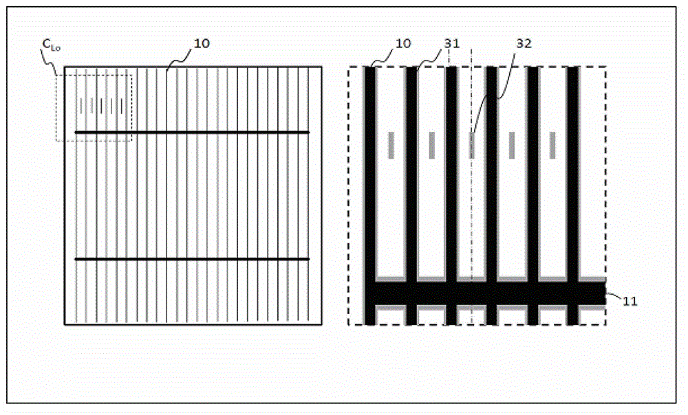
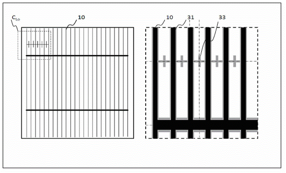
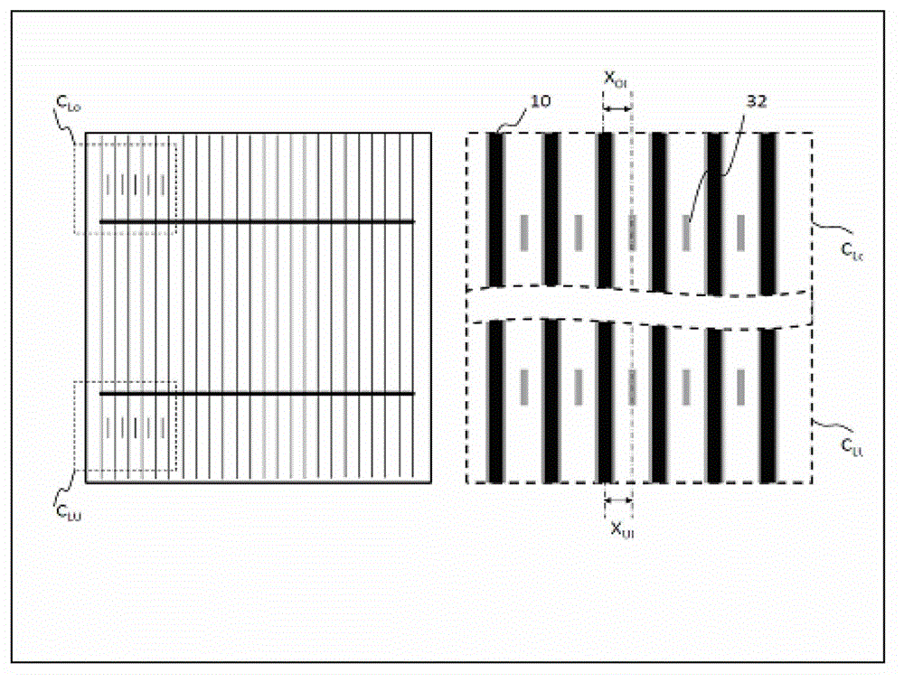
[0039] refer to figure 1 , figure 2 , image 3 with Figure 4 , the detection method of the printing position accuracy of the grid lines of selective electrode type solar cells, a mark pattern is generated on the light-receiving surface of the battery sheet, and after the metal grid line is printed, the distance between the metal grid line and the mark pattern is measured, and the mark pattern and the mark pattern are combined. The distance from the center line of the selective re-diffusion area determines the coincidence accuracy of the grid line printing position and the selective re-diffusion area. The method can detect the coincidence accuracy of the printing position of the metal grid line and the selective re-diffusion area, that is, the pr...


PUM


Abstract

The invention relates to the field of detection control, in particular to a selective electrode type solar cell grid line printing position precision detecting method. A mark pattern is generated on a light-receiving surface of a cell plate; after a metal grid line is printed, the distance between the metal grid line and the mark pattern is measured; the superposition precision between a grid line printing position and a selective re-diffusion area is judged by combining the distance between the mark pattern and the selective re-diffusion area. The superposition precision between the grid line printing position and the selective re-diffusion, i.e. the grid line printing position precision can be detected.

Description

technical field [0001] The invention relates to the field of detection and control, in particular to a detection method in the production process of solar cells. Background technique [0002] The electron-hole pairs in crystalline silicon solar cells enter the excited state from the steady state under the action of photons, and part of the electron-hole pairs in the excited state are separated into electrons and holes. When the external circuit is turned on, a current loop is formed to realize the light Energy to electrical energy conversion. [0003] The so-called selective electrode solar cell, also called selective emitter crystalline silicon solar cell, is heavily doped at the contact between the metal gate (electrode) and the silicon wafer, and lightly doped at the position between the electrodes. Such a structure makes the light-receiving surface of the selective electrode type crystalline silicon solar cell have high square resistance characteristics, which can impro...

Claims


Application Information

Patent Timeline
Patent Type & Authority Applications(China)
IPC IPC(8): B41F33/00G01B11/00
Inventor 于国丰卞莉
Owner SHENBEN ELECTRICAL TECH SHANGHAI
Learn More