Device and method for removing ash in smoke box of waste heat boiler

A waste heat boiler and ash cleaning device technology, which is applied in the direction of combustion methods, solid residue removal, lighting and heating equipment, etc., can solve the problems of reduced boiler service life, incomplete ash cleaning, and dead ends in purging, so as to improve work efficiency. Efficiency, prolonging service life, and avoiding the effects of over-culture

Inactive Publication Date: 2014-10-15
汪家权
View PDF7 Cites 3 Cited by
  • Summary
  • Abstract
  • Description
  • Claims
  • Application Information

AI Technical Summary

Problems solved by technology

For example, cleaning with a steam soot flusher means installing multiple soot flushers on the boiler to flush the boiler intermittently. There are dead angles, incomplete ash removal, and high operating cost of the ash cleaner. If compressed air is used to flush ash, it will also cause large-scale oxidation in the boiler and reduce the service life of the boiler; mechanical vibration for ash removal, mechanical vibration device It uses a small-capacity motor as the power, drives a long shaft through the transmission to rotate at a low speed, hangs many vibrating hammers on the shaft according to the phase of equal division, and hammers the heating surface of the boiler in sequence. The heated surface generates strong vibrations, causing the adhered ash to undergo repeated stress and produce tiny cracks until the adhesion of the ash is destroyed and falls off. The advantage of mechanical vibration is that it consumes less power and does not affect the smoke. Gas to add additional medium, but the disadvantage is that it has a certain degree of adverse effect on the service life and strength of the boiler tube and weld seam, shortening the service life of the boiler as a whole and loosening of other parts; periodic shutdown of the boiler to spray water and soot , this cleaning method requires periodic shutdown of the furnace, which has a great limit on the cleaning time, and it cannot be cleaned in time, which will reduce the working efficiency of the boiler
Therefore, the dust cleaning methods of waste heat boiler smoke boxes in the prior art all have great defects, and cannot meet the requirements of using waste heat boilers in the prior art

Method used


Image

  • Device and method for removing ash in smoke box of waste heat boiler
  • Device and method for removing ash in smoke box of waste heat boiler
  • Device and method for removing ash in smoke box of waste heat boiler

Examples


Embodiment Construction

[0017] In order to facilitate those skilled in the art to understand the technical solution of the present invention, the technical solution of the present invention will be further described in conjunction with the accompanying drawings.

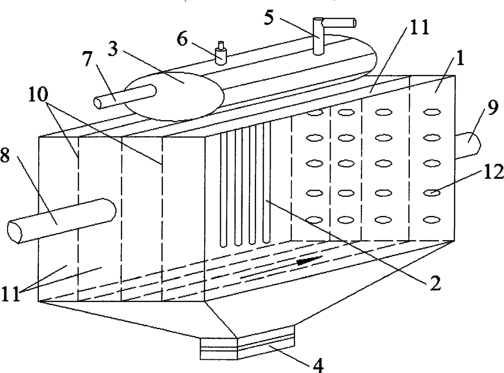
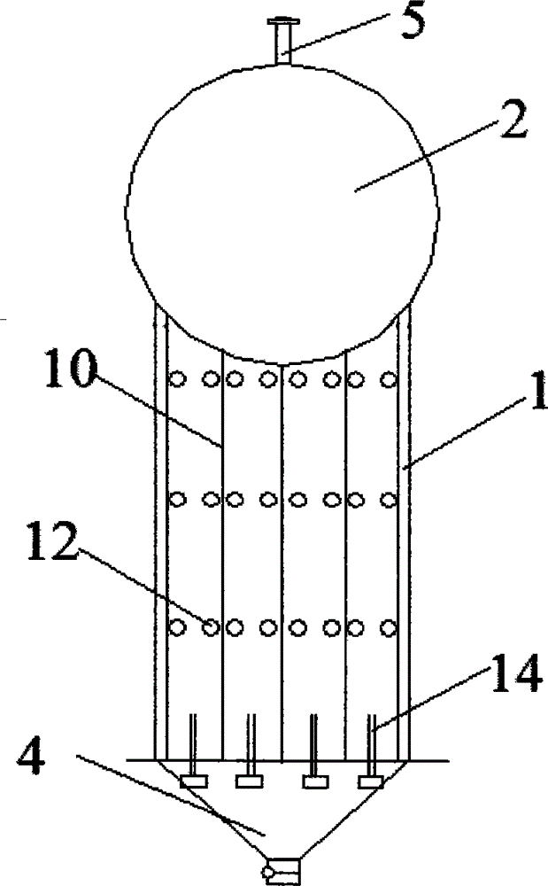
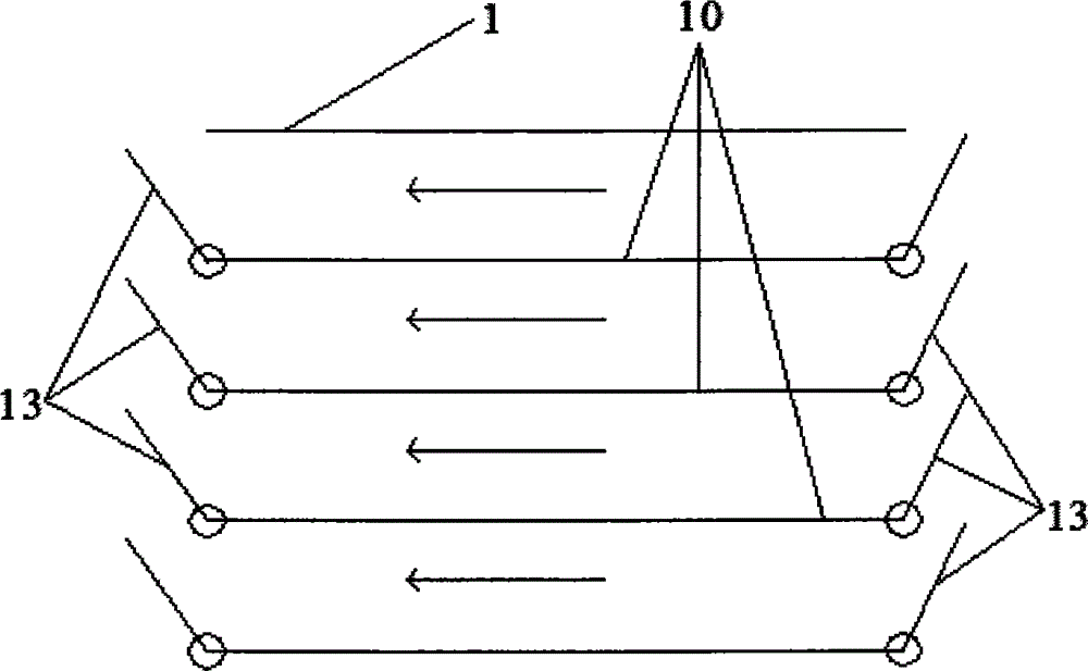
[0018] like figure 1 , figure 2 and image 3 As shown, a waste heat boiler smoke box dust removal device includes a smoke box 1, a heat absorption pipe 2 is arranged inside the smoke box 1, a steam pressure bag 3 is arranged on the top, an ash discharge port 4 is arranged on the bottom, and the steam pressure bag 3 is arranged on the top A steam exhaust pipe 5, a safety valve 6 and a one-way water inlet pipe 7 are provided. The water inlet pipe 7 is connected to the heat-absorbing pipe 2 inside the smoke box 1. A high-temperature flue gas inlet pipe 8 is connected to one side of the smoke box 1, and is connected to a A flue gas outlet pipe 9 is connected to the opposite side of the flue gas inlet pipe 8, and a partition 10 parallel to th...


PUM


Abstract

The invention discloses a device for removing ash in a smoke box of a waste heat boiler. The device comprises the smoke box. Heat absorbing pipes are arranged inside the smoke box, a steam pressure pocket is arranged on the top of the smoke box, an ash discharge outlet is formed in the bottom of the smoke box, a steam exhaust pipe, a safety valve and a one-way water inlet pipe are arranged on the top of the steam pressure pocket, the water inlet pipe is connected with the heat absorbing pipes inside the smoke box, a high-temperature smoke inlet pipe is connected onto a side surface of the smoke box, a smoke outlet pipe is connected to the side surface, which is opposite to the side surface connected with the smoke inlet pipe, of the smoke box, partition plates which are parallel to a smoke movement direction are arranged inside the smoke box, an internal space of the smoke box is divided into at least two chambers by the partition plates, chamber doors are arranged at two ends of each chamber, and ash flushing pipes are arranged in each chamber and are connected with blowdown pipelines and blowdown valves of the boiler. According to the technical scheme, the device for removing the ash has the advantages that the ash can be removed without stopping the boiler, and accordingly the work efficiency can be improved; vibration and the like on the smoke box can be omitted when the ash is removed, accordingly, the smoke box can be prevented from being damaged, and the service life of the smoke box can be prolonged.

Description

technical field [0001] The invention belongs to the field of waste heat boiler dust removal, and more specifically relates to a waste heat boiler smoke box dust removal device and a dust cleaning method for removing dust in the smoke box during the continuous operation of the waste heat boiler. Background technique [0002] The waste heat boiler uses the residual heat in the flue gas to heat the heat-absorbing pipe, thereby heating the water passing through the heat-absorbing pipe. In this way, the waste heat boiler greatly improves the utilization rate of the heat released by fuel combustion, so the waste heat boiler has a better Energy-saving performance, widely used. However, the hot flue gas of the waste heat boiler contains a large amount of dust, and the dust is fine, and it is easy to accumulate dust on the heat-absorbing pipe inside, which affects the heat transfer effect of the boiler heating surface, etc., resulting in a reduction in the utilization rate of boiler ...

Claims


Application Information

Patent Timeline
Patent Type & Authority Applications(China)
IPC IPC(8): F23J3/02
Inventor 汪家权刘付军刘睿哲
Owner 汪家权
Why Eureka
Try Eureka