
A Fiber Bragg Grating Strain Gauge Simultaneously Measuring Reinforcement Temperature and Strain

A fiber grating and strain gauge technology, applied in thermometers, thermometers with physical/chemical changes, measuring devices, etc., can solve the problem that vibrating wire steel bar strain gauges cannot perform dynamic testing, cannot meet high precision and long-term monitoring, and cannot be realized. Distributed measurement and other issues, to achieve the effects of broad engineering application prospects, strong anti-electromagnetic interference ability, and simple structure

Active Publication Date: 2016-08-17
HOHAI UNIV
View PDF7 Cites 0 Cited by
  • Summary
  • Abstract
  • Description
  • Claims
  • Application Information

AI Technical Summary

Problems solved by technology

Traditional steel bar strain gauges are based on the principle of resistance strain sensing or vibrating wire sensing. The test signal is susceptible to electromagnetic interference, the reliability of long-term monitoring results is poor, distributed measurement cannot be realized, the wires are complicated, and the vibrating wire steel bar strain gauge cannot Disadvantages such as dynamic testing
When installing the traditional steel bar strain gauge, it is necessary to cut off the steel bar to be measured, and then weld the steel bar strain gauge in the shape of steel bar to the cut-off position of the steel bar to be tested. Due to the protrusion of the welded part, the force transmission state of the joint surface between the steel bar and the concrete changes. As a result, changes in the stress state of the measured steel bars in reinforced concrete structures have disadvantages such as limited accuracy, complicated installation, and great impact on the measured structure.
Therefore, the existing steel bar strain gauges for reinforced concrete structures cannot meet the needs of high precision and long-term monitoring, and there is an urgent need for a steel bar strain gauge with superior performance

Method used


Image

  • A Fiber Bragg Grating Strain Gauge Simultaneously Measuring Reinforcement Temperature and Strain
  • A Fiber Bragg Grating Strain Gauge Simultaneously Measuring Reinforcement Temperature and Strain
  • A Fiber Bragg Grating Strain Gauge Simultaneously Measuring Reinforcement Temperature and Strain

Examples


Embodiment

[0025] Embodiment: Below in conjunction with Figure 1-10 The technical scheme of the present invention is described in detail:

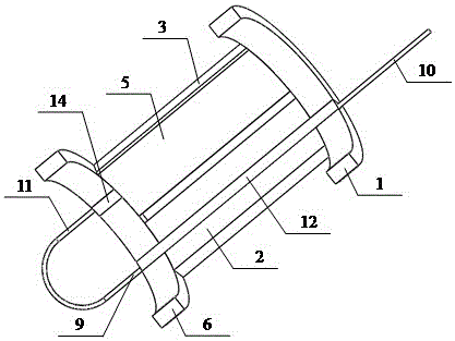
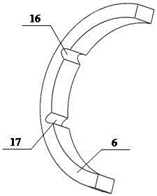
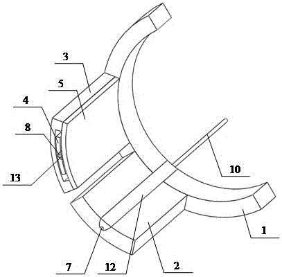
[0026] A fiber grating strain gauge for simultaneously measuring steel bar temperature and strain in this embodiment includes a first arc-shaped metal sheet 1, a grooved arc-shaped metal connecting piece 2, an arc-shaped flanged metal connecting piece 3, a Groove arc-shaped metal intermediate sheet 4, arc-shaped metal connecting sheet 5, second arc-shaped metal sheet 6, first bare fiber grating 7, second bare fiber grating 8, first pigtail 9, second tail Fiber 10, third pigtail 11, first epoxy resin 12, second epoxy resin 13, third epoxy resin 14, first groove 15, second groove 16 and third groove 17, wherein, The first arc-shaped metal sheet 1 is provided with a first groove 15 , and the second arc-shaped metal sheet 6 is provided with a second groove 16 and a third groove 17 .

[0027]Remove the coating layer from the grating section of the seco...


PUM


Abstract

The invention provides an optical fiber grating strain gauge for simultaneously measuring the temperature and strain of steel bars. It utilizes multi-section arc-shaped metal sheets with the same diameter as the steel bar to be measured to connect each other to form the main structure of the sensor. The arc-shaped metal connecting piece with flange and The arc-shaped metal connecting piece forms a cavity, and the two ends of the cavity and the grooved arc-shaped metal connecting piece parallel to the cavity are respectively connected with an arc-shaped metal sheet. Arc-shaped metal middle piece. The first bare fiber grating is fixed in the groove of the arc-shaped metal connecting sheet with grooves to form a fiber grating strain sensor, and the second bare fiber grating is fixed in the groove of the arc-shaped metal intermediate sheet with grooves to form a fiber grating temperature sensor. The temperature measurement value of the fiber grating temperature sensor is used to compensate the strain measurement value of the fiber grating strain sensor, so as to achieve the simultaneous measurement of steel bar strain and temperature. The strain gauge has high precision and small size, and has wide engineering application prospects.

Description

technical field [0001] The invention relates to a steel bar strain and temperature measuring device, in particular to a sensor for simultaneously measuring the steel bar strain and the temperature at a measuring point in a civil engineering reinforced concrete structure. Background technique [0002] Reinforcement strain is one of the main parameters reflecting the stress state of reinforced concrete structures. Whether it is model experiments or actual engineering structure performance monitoring, reinforcement strain is an important content of reinforced concrete structure testing. Traditional steel bar strain gauges are based on the principle of resistance strain sensing or vibrating wire sensing. The test signal is susceptible to electromagnetic interference, the reliability of long-term monitoring results is poor, distributed measurement cannot be realized, the wires are complicated, and the vibrating wire steel bar strain gauge cannot Disadvantages such as dynamic test...

Claims


Application Information

Patent Timeline
Patent Type & Authority Patents(China)
IPC IPC(8): G01B11/16G01K11/32G01K11/3206
Inventor 周广东胡锦林张欢
Owner HOHAI UNIV
Learn More