Lesion area imaging system and method

An imaging system and lesion area technology, applied in the field of medical devices, can solve problems such as poor image quality, and achieve the effects of low energy, improved detection efficiency, and improved quality

Inactive Publication Date: 2014-10-15
SHENZHEN INST OF ADVANCED TECH
View PDF3 Cites 4 Cited by
  • Summary
  • Abstract
  • Description
  • Claims
  • Application Information

AI Technical Summary

Problems solved by technology

[0004] Based on this, it is necessary to provide a lesion area imaging system that can improve the quality of images obtained by imaging in order to solve the problem of poor image quality of traditional imaging equipment.

Method used


Image

  • Lesion area imaging system and method
  • Lesion area imaging system and method
  • Lesion area imaging system and method

Examples


Embodiment Construction

[0038] In order to make the object, technical solution and advantages of the present invention clearer, the present invention will be further described in detail below in conjunction with the accompanying drawings and embodiments. It should be understood that the specific embodiments described here are only used to explain the present invention, not to limit the present invention.

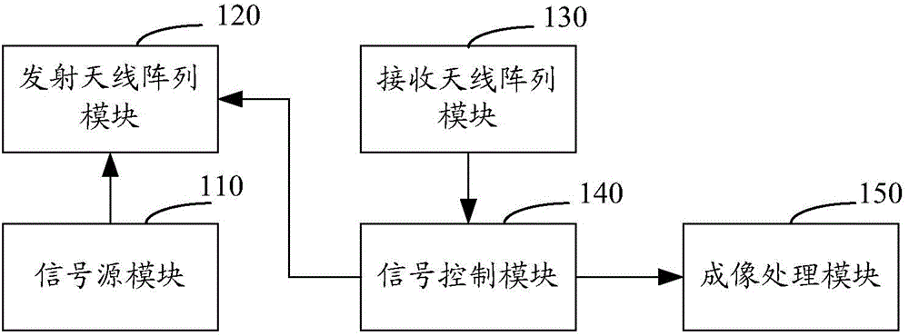
[0039] figure 1 It is a structural block diagram of a lesion area imaging system in an embodiment. Such as figure 1 As shown, a lesion imaging system includes a signal source module 110 , a transmitting antenna array module 120 , a receiving antenna array module 130 , a signal control module 140 and an imaging processing module 150 . The transmitting antenna array module 120 is connected to the signal source module 110 , and the signal control module 140 is connected to the receiving antenna array module 130 , the transmitting antenna array module 120 and the imaging processing module 150 respect...


PUM


Abstract

The invention relates to a lesion area imaging system and method. The system comprises a signal source module, a transmitting antenna array module, a receiving antenna array module, a signal control module and an image processing module. The signal source module is used for generating a pulse signal. The transmitting antenna array module is used for transmitting the pulse signal to a lesion area. The receiving antenna array module is used for receiving a first echo signal which is generated for the pulse signal. The signal control module is used for carrying out time inversion on the first echo signal to acquire an inversion signal. The transmitting antenna array module is further used for transmitting the inversion signal to the lesion area. The receiving antenna array module is further used for receiving a second echo signal which is generated for the inversion signal. The signal control module is further used for extracting target information in the second echo signal. The image processing module is used for carrying out imaging according to the target information. The signal-to-noise ratio is improved, and the image quality is improved.

Description

technical field [0001] The invention relates to the field of medical devices, in particular to a lesion area imaging system and method. Background technique [0002] In order to understand the health status of the human body, hospitals often use some imaging equipment to perform imaging tests on the human body. For example, X-ray imaging technology, optical imaging technology, ultrasonic imaging technology or nuclear magnetic resonance imaging is used to image and detect the inside of the human body to obtain images of the inside of the human body. [0003] However, traditional imaging equipment is prone to channel fading during imaging, which reduces the signal-to-noise ratio of the image, and the quality of the resulting image is poor. Contents of the invention [0004] Based on this, it is necessary to provide a lesion area imaging system that can improve the quality of images obtained by imaging to solve the problem of poor image quality of traditional imaging equipme...

Claims


Application Information

Patent Timeline
Patent Type & Authority Applications(China)
IPC IPC(8): G01S13/89G01S7/292
CPCA61B5/00
Inventor 张宁王亮
Owner SHENZHEN INST OF ADVANCED TECH
Why Eureka
Try Eureka