

Construction machinery
A technology for construction machinery and work, which is applied in the direction of mechanical equipment, soil movers/shovels, fluid pressure actuators, etc., can solve problems such as the timing of regeneration and use of energy that does not involve energy, so as to extend the operating time and reduce fuel consumption. Consumption, productivity improvement effect
- Summary
- Abstract
- Description
- Claims
- Application Information
AI Technical Summary
Problems solved by technology
Method used
Image

Examples
Embodiment 1
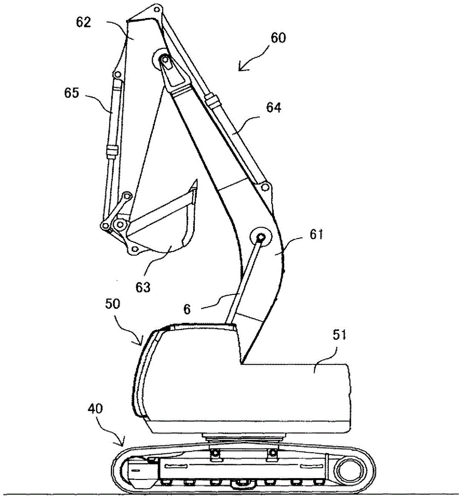
[0033] exist figure 1 Among them, the electrohydraulic excavator has a running body 40 , a revolving body 50 rotatably provided on the running body 40 , and an excavating mechanism 60 mounted on the revolving body 50 .
[0034] The excavating mechanism 60 includes a boom 61 , a boom hydraulic cylinder 6 for driving the boom 61 , an arm 62 rotatably supported near the top end of the boom 61 , an arm hydraulic cylinder 64 for driving the arm 62 , The bucket 63 pivotally supported on the tip of the arm 62 so as to be rotatable, and the bucket hydraulic cylinder 65 for driving the bucket 63 are configured.
[0035] A prime mover chamber 51 for accommodating an engine, a main pump, etc. which will be described later is provided at the rear of the rotating body 50 .
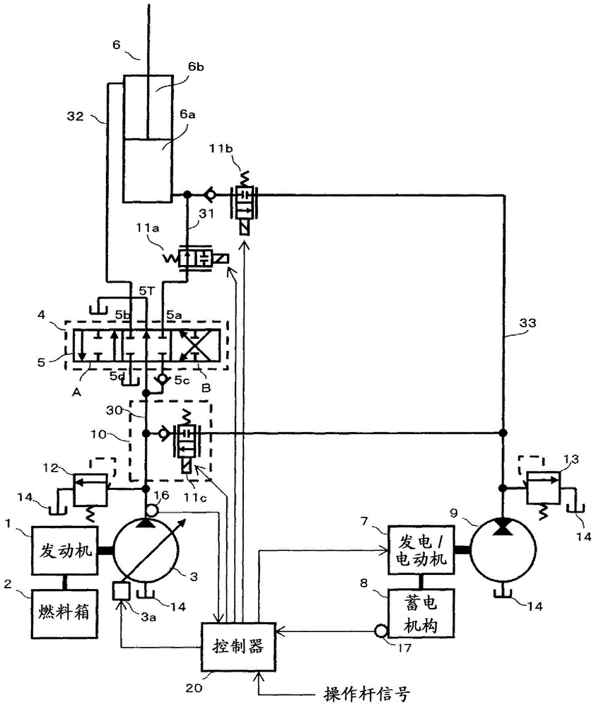
[0036] Next, use figure 2 The system structure of the electric / hydraulic equipment of the hydraulic excavator will be described. In addition, in the present embodiment, the boom cylinder 6 will be described as an e...
Embodiment approach
[0096] According to the above-mentioned first embodiment of the construction machine of the present invention, it is possible to provide a construction machine capable of reducing the power of the engine 1 which is a power source by efficiently using recovered energy, and significantly reducing the fuel consumption of the entire construction machine. As a result, productivity is improved because the operation time of the construction machine is extended.
[0097] Furthermore, in this embodiment, Figure 5 A case where the change in the target value of the discharge flow rate of the hydraulic pump motor 9 and the main pump 3 is designed to be stepped is shown, but the present invention is not limited thereto. For example, it is also possible to make it change smoothly.
[0098] In addition, when the fluctuation of the discharge pressure is large, the controller 20 may also use the signal of the discharge pressure subjected to averaging processing (low-pass filter processing) i...
Embodiment 2
[0100] Hereinafter, a second embodiment of the construction machine of the present invention will be described with reference to the drawings. Figure 9 It is a system configuration diagram of the electric / hydraulic equipment constituting the second embodiment of the construction machine of the present invention. exist Figure 9 in, with Figure 2 to Figure 8 The same reference numerals as shown indicate the same parts, and thus detailed description thereof will be omitted.
[0101] Figure 9 The shown second embodiment of the construction machine of the present invention is composed of substantially the same equipment as the first embodiment, but the following structures are different.
[0102]In the first embodiment, the hydraulic oil supply circuit 10 is constituted by the switching valve 11c as the hydraulic oil switching unit, and the presence or absence of the hydraulic oil discharged from the hydraulic pump motor 9 is controlled in accordance with an instruction from...
PUM
 Abstract
Description
Claims
Application Information