Intercooling or intercooling recuperating layout for aero-engine

A technology of aero-engine and regenerative cycle, applied in the cooling of engine, engine components, machine/engine, etc., can solve the problem of difficulty in meeting the rapid response of aero-engine, large mass of intercooler and regenerator, and increasing the weight of the whole engine. and other problems, to achieve the effect of light weight, high heat exchange efficiency and compact structure

Active Publication Date: 2014-10-22
BEIHANG UNIV
View PDF5 Cites 19 Cited by
  • Summary
  • Abstract
  • Description
  • Claims
  • Application Information

AI Technical Summary

Problems solved by technology

[0003] At present, there are still many defects in the layout of the conventional intercooling and heat recovery cycle: the addition of the intercooler heat exchanger and the heat recovery heat exchanger makes the mainstream flow path bend back and forth, causing great losses along the way; the structure is complex and the core machine is difficult to maintain; The intercooler and regenerator have a large mass, and the heat transfer per unit mass is low, which greatly increases the overall weight of the engine; the heat transfer response speed is slow and it is difficult to meet the requirements of the aero-engine for rapid response to changing operating conditions
Because these problems have not been solved, although the concept of intercooling and heat recovery cycle has been proposed for a long time, it has not been applied to high-thrust aero-engine models at present.

Method used


Image

  • Intercooling or intercooling recuperating layout for aero-engine
  • Intercooling or intercooling recuperating layout for aero-engine
  • Intercooling or intercooling recuperating layout for aero-engine

Examples


Embodiment Construction

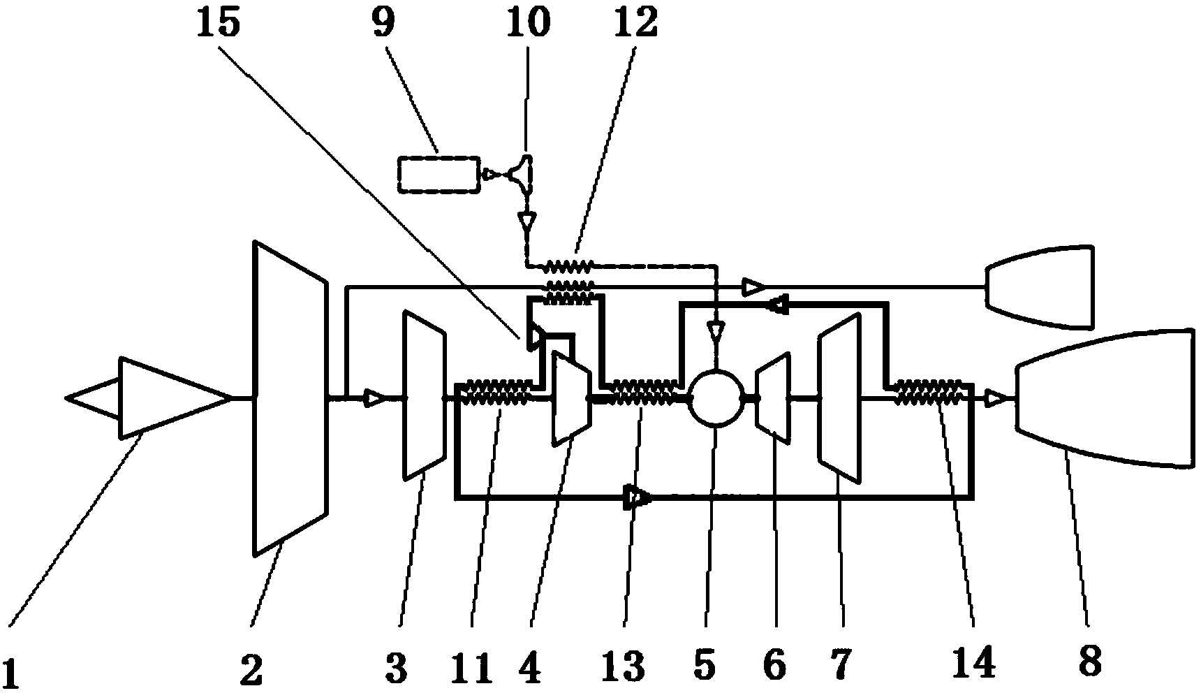
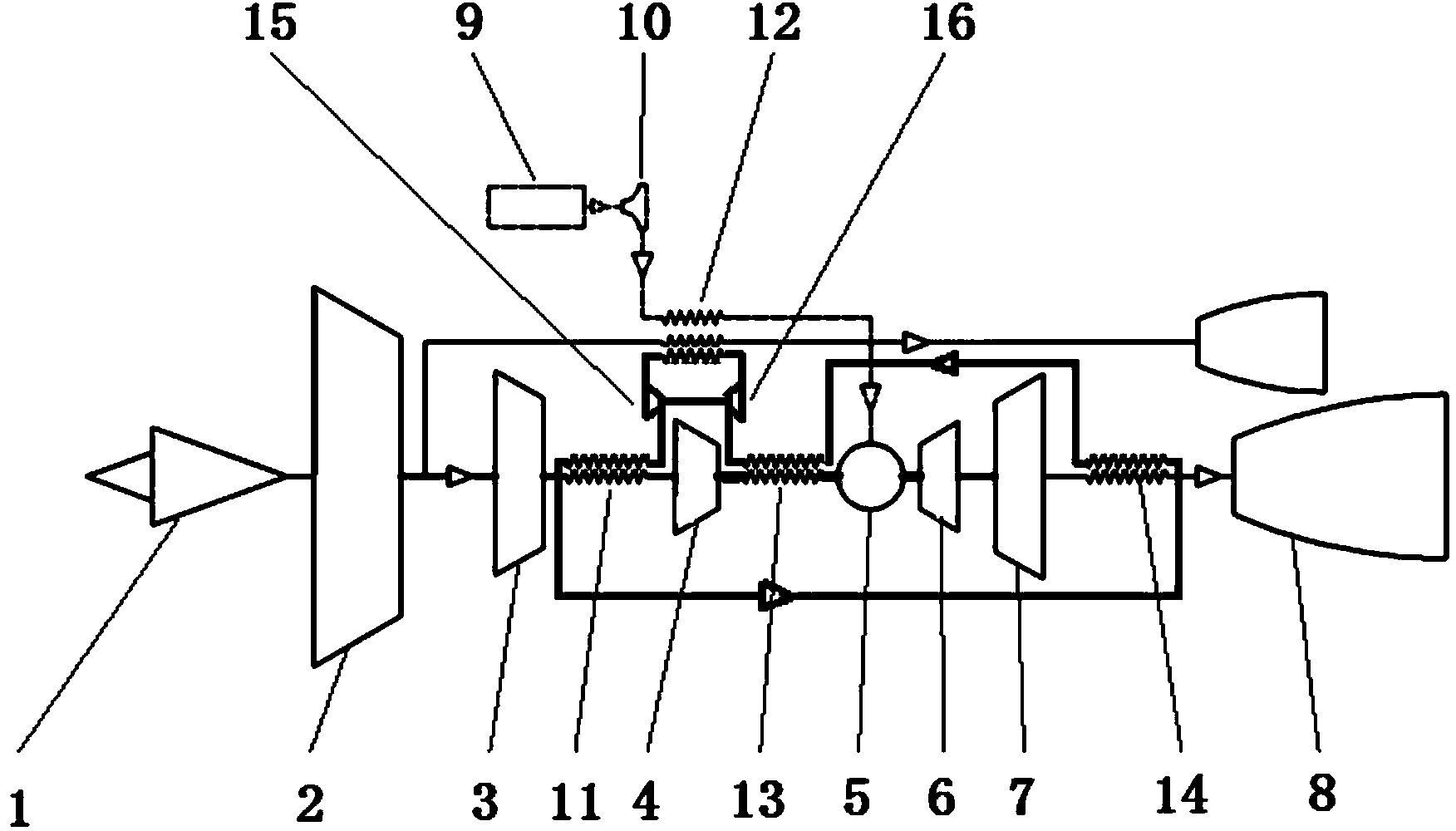
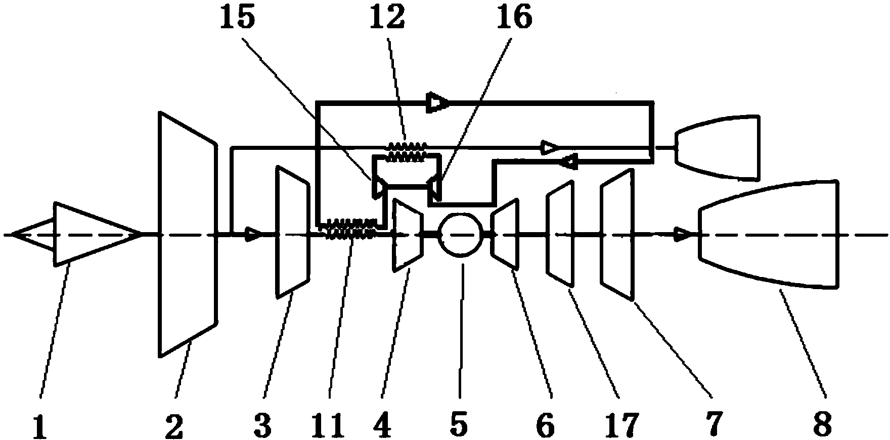
[0031] The invention can be used in the layout of the intercooling or intercooling heat recovery cycle in the fields of aeroengines, ground gas turbines and the like. The following implementation cases of the present invention are implemented on the basis of a certain type of large bypass ratio three-rotor civil aeroengine scheme, and a supercritical fluid circulation is added to its original flow path to form an intercooling cycle. Such as image 3As shown, the upper part is the intercooling circulation layout scheme, and the lower part is the conventional circulation layout scheme for comparison. The Brayton cycle in the mainstream flow path of the intercooling cycle layout scheme includes: intake duct 1, fan 2, medium-pressure compressor 3, high-pressure compressor 4, combustion chamber 5, high-pressure turbine 6, medium-pressure turbine 17, and low-pressure turbine 7. Exhaust nozzle 8, the above-mentioned components are arranged from front to back in numerical order and c...


PUM


Abstract

The invention provides an intercooling or intercooling recuperating layout for an aero-engine. The layout comprises a Brayton cycle in a main flow path and a supercritical state fluid cycle, wherein the two cycles are mutually independent and are coupled through a micro-scale heat exchanger. The micro-scale heat exchanger is a supercritical micro-scale compact rapid heat exchanger comprising a heat exchanging element and two working mediums, wherein the two working mediums exchange heat through the heat exchanging element. The micro-scale heat exchanger is characterized in that one of the working mediums employs a supercritical state fluid, the other working medium is not limited, the size of the heat exchanging element is in a micro-scale range, the critical pressure of the supercritical state fluid is at least 0.5 MPa, the temperature of the supercritical state fluid is at least 200 DEG C higher than critical temperature, and micro-scale refers to that the geometric scale of the basic heat exchanging element is no more than 2 mm. The intercooling or intercooling recuperating layout provided by the invention overcomes the disadvantages of conventional intercooling or intercooling recuperating layouts, improves the cycle efficiency of the aero-engine and reduces the oil consumption rate of the aero-engine.

Description

technical field [0001] The invention relates to the technical field of aeroengines, in particular to an intercooling or intercooling heat recovery cycle layout of an aeroengine, which is mainly used to improve the working performance of an aeroengine. Background technique [0002] Further improving the performance of aero-engines and reducing fuel consumption is of great significance to the economy and environmental protection of aero-engines, and has always been the goal pursued by the field of aero-engines. As an effective way to reduce fuel consumption, the intercooling and heating cycle has become one of the research hotspots in recent years. The intercooling cycle means that the gas is fully cooled before entering the high-pressure compressor to reduce the inlet temperature of the high-pressure compressor, thereby increasing the Mach number at the inlet of the high-pressure compressor, reducing the power required by the compressor, and improving the engine cycle efficie...

Claims


Application Information

Patent Timeline
Patent Type & Authority Applications(China)
IPC IPC(8): F02C7/143F02C7/14
Inventor 邹正平刘火星陈懋章武翼飞唐海龙
Owner BEIHANG UNIV
Why Eureka
Try Eureka