
Built-in smoke box type soot blower for horizontal type fire tube boiler

A fire-tube boiler and soot blower technology, which is applied in the treatment of combustion products, combustion methods, and removal of solid residues, etc., can solve the problems of decreased heat transfer coefficient, difficulty in blowing soot, and labor and labor, and achieve low operating costs. , Reduce the mechanical and electrical failure rate and maintenance rate, and the effect of small one-time investment

Inactive Publication Date: 2014-10-22
JIANGSU SHUANGLIANG BOILER
View PDF6 Cites 2 Cited by
  • Summary
  • Abstract
  • Description
  • Claims
  • Application Information

AI Technical Summary

Problems solved by technology

But coke oven gas contains NH 3 、H 2 S. The tar and ash are not cleaned before combustion, resulting in pollution and dust accumulation on the heating surface after combustion, resulting in a decrease in the heat transfer coefficient, and the impurities in the gas are easily deposited on the heating surface to cause blockage
Using high-speed steam or compressed air to blow off soot deposits is a common way of soot blowing, which is easy to operate and has a wide range of sources. However, due to the structural limitations of horizontal fire tube boilers, it is difficult to achieve soot blowing. Shut down the furnace, open the door of the smoke box, and use the smoke pipe brush to remove the dust. This method is laborious and laborious, and it may not be able to clean it up

Method used


Image

  • Built-in smoke box type soot blower for horizontal type fire tube boiler
  • Built-in smoke box type soot blower for horizontal type fire tube boiler
  • Built-in smoke box type soot blower for horizontal type fire tube boiler

Examples


Embodiment Construction

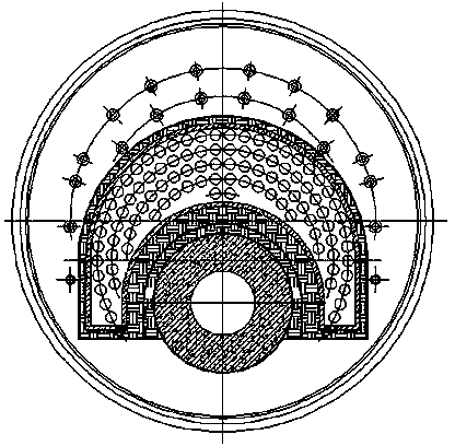
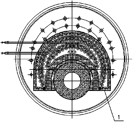
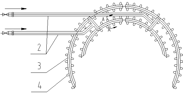
[0022] See Figure 2-4 , figure 2 It is a schematic diagram of a soot blower built into the flue box of a horizontal fire tube boiler. image 3 It is a schematic diagram of the structure of the sootblower of the present invention. Figure 4 for image 3 A-A cutaway view. by Figure 2-4 It can be seen that the horizontal fire tube boiler of the present invention has a built-in smoke box type soot blower, which is built in the front smoke box or the rear smoke box of the horizontal fire tube boiler, and is mainly composed of the main pipe 2, the branch pipe 3 and the nozzle 4. The main pipe 2 is connected to the branch pipe 3. The branch pipe 3 has multiple rows, and the multiple rows of branch pipes 3 are arranged in a ring shape. The arrangement position corresponds to the position of each exhaust pipe in the front smoke box or the rear smoke box of the horizontal fire tube boiler. A number of nozzles 4 are arranged on the branch pipe 3, and the arrangement position of each n...


PUM


Abstract

The invention relates to a built-in smoke box type soot blower for a horizontal type fire tube boiler. The built-in smoke box type soot blower is mainly used for boiler soot blowing of fuels such as burning heavy oil and coke oven gas which are high in ash content. The soot blower is arranged in a front smoke box or a rear smoke box of the horizontal type fire tube boiler and comprises a main pipe (2), branch pipes (3) and nozzles (4). The main pipe (2) is connected with the branch pipes (3), a plurality of rows of branch pipes (3) are annularly arranged, the arrangement positions of the branch pipes (3) correspond to the positions of each row of smoke pipes in the front smoke box or the rear smoke box of the horizontal type fire tube boiler, each row of branch pipes (3) are provided with a plurality of nozzles (4), and the arranging position of each nozzle (4) on the branch pipe (3) corresponds to the inlet position of each smoke pipe in the front smoke box or the rear smoke box of the horizontal type fire tube boiler. According to the built-in smoke box type soot blower, high-speed gas is utilized to blow deposited soot in the longitudinal smoke pipes to the other end of each pipe, and collection and tidying of the deposited soot are facilitated.

Description

Technical field [0001] The invention relates to a built-in smoke box type soot blower for a horizontal fire tube boiler. Mainly used for soot blowing in boilers with higher ash content such as heavy oil and coke oven gas. Background technique [0002] Among the liquid fuels, heavy oil has a price advantage that light diesel oil cannot match, but heavy oil has high ash content and is easy to accumulate during operation. Coke-oven gas is a by-product of coke produced by high-temperature coking in isolation of air, referred to as coke-oven gas, which is a combustible gas obtained from the coking process of coal. But the coke oven gas contains NH 3 , H 2 S. Tar and ash are not cleaned before combustion, which leads to pollution and ash accumulation on the heated surface after combustion, resulting in a decrease in heat transfer coefficient, and it is easy to cause impurities in the gas to deposit on the heated surface and cause blockage. Using high-speed steam or compressed air to ...

Claims


Application Information

Patent Timeline
Patent Type & Authority Applications(China)
IPC IPC(8): F23J3/02
Inventor 许清王凌殷陈曦杨戈刘耸张宏
Owner JIANGSU SHUANGLIANG BOILER
Learn More