Pull-out force tester and its test method

A drawing force and detector technology, applied in force/torque/work measuring instruments, testing of mechanical parts, testing of machine/structural parts, etc. The effect of high motion accuracy, improving test accuracy and reducing deviation

Inactive Publication Date: 2016-08-24
SHENZHEN POLYTECHNIC
View PDF10 Cites 0 Cited by
  • Summary
  • Abstract
  • Description
  • Claims
  • Application Information

AI Technical Summary

Problems solved by technology

[0005] However, in the process of applying the above-mentioned patented automatic testing machine products, the company found the following problems: (1) The automatic testing machine lacks equipment for its calibration, whether the measurement data of the automatic testing machine is accurate or not, and it is difficult for users to calibrate the testing equipment, and there is a lack of basis; (2) The automatic testing machine only measures the maximum pulling force, and automatically sorts the products according to this parameter, and only caches the maximum pulling force of 10 latest tested products in the PLC memory, and displays them on the LCD screen. Provide the force change data of the whole drawing process; (3) Based on the reason of (2), it is difficult to obtain the data of the drawing force of a batch of samples, and the data analysis of the drawing force cannot be realized, so it cannot be used for the equipment in the production-related process section. Appropriate adjustments to increase the rate of excellent products and reduce the rate of rework and scrap are to provide a reference for improving the production process

Method used


Image

  • Pull-out force tester and its test method
  • Pull-out force tester and its test method
  • Pull-out force tester and its test method

Examples


Embodiment 1

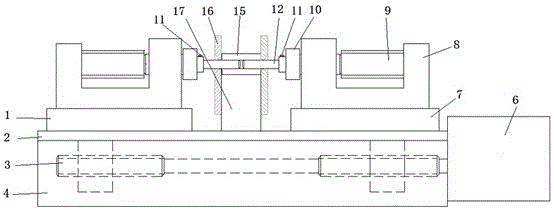
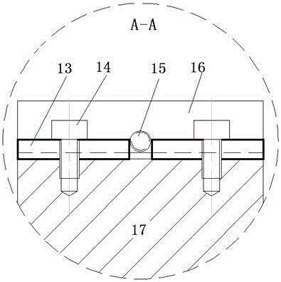
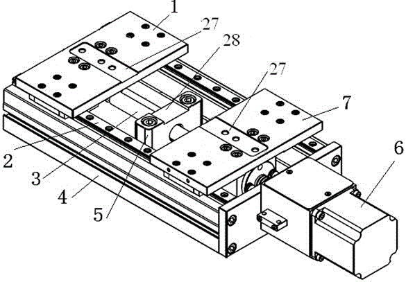
[0047] The pull-out force detector in the present embodiment is as figure 1 As shown, it includes a base 4 and a slide rail 2 installed on the base 4 . A left slide 1 and a right slide 7 are installed on the slide rail 2, and a probe base 8 is respectively installed on the left slide 1 and the right slide 7, and the two probe bases 8 respectively clamped in the probe seat positioning grooves 27 on the left slide 1 and the right slide 7; each probe seat 8 is provided with a detection ferrule 12 and a clamping head 10 and the force sensor 9, wherein the detection ferrule 12 is fastened and fixed on one side of the clamping head 10 by a locking screw 11, and the other side of the clamping head 10 is connected with the force sensor 9, and at the same time The clamping head 10 is also floatingly connected with the probe base 8 ; the detection ferrules 12 on the two probe bases 8 are oppositely arranged. As a preferred implementation mode, the left sliding table 1 and the right sl...

Embodiment 2

[0056] On the basis of the pull-out force detector described in Embodiment 1, the pull-out force detector in the present embodiment is provided with a photoelectric switch on the stepper motor; in addition, the pull-out force in the present embodiment Detector is also provided with single-chip microcomputer system 20, and described single-chip microcomputer system 20 comprises:

[0057] Pulling force acquisition module 18 is connected with the force sensor 9, and the pulling force acquisition module 18 collects the voltage output signal of the force sensor 9 in real time through the A / D conversion channel, and converts it into pulling force data information;

[0058] Operational processing module 23, is connected with described pulling force acquisition module 18 and is arranged, receives the pulling force data information that described pulling force acquisition module 18 transmits and carries out arithmetic processing;

[0059] Digital I / O module 24, used for the input of th...


PUM


Abstract

The invention discloses a two-way drawing force detector for a precision casing and a testing method thereof. The stepping motor is arranged at one end of the lead screw, the fixture supporting seat is arranged in the middle of the base, and the fixture for fixing the ceramic casing sample is arranged on the fixture supporting seat, and the left and right sliding tables are fixedly installed with opposite Two detection heads, each detection head is composed of detection ferrule, connecting parts and force sensor, the stepping motor can drive the double-headed screw and drive the detection heads on the left and right sliding tables to the ceramic sleeve workpiece on the fixture. Centering insertion, pull-out pull force detection motion. Its equipment has high precision and small vibration, and it is equipped with a stepping motor return position reset limit switch, which reduces the deviation of the detection head on the slide table during reciprocating motion, improves the test accuracy of the pulling force detector, and can be used as an automatic detection machine calibration instrument.

Description

technical field [0001] The invention relates to the technical field of precision parts detection, and specifically discloses a precision casing bidirectional pullout force detector and a testing method thereof. Background technique [0002] The precision sleeve involved in the present invention belongs to the optical fiber connector. The optical fiber connector is a device for detachable (movable) connection between the optical fiber and the optical fiber. The energy can be coupled into the receiving optical fiber to the greatest extent, and the impact on the system caused by its intervention in the optical link is minimized. There are many types of fiber optic connectors, which can be divided into FC, SC, ST, MU, LC, etc. according to the connection method; according to the casing material, they can be divided into zirconia ceramic materials, SUS materials, glass materials, plastic materials, metal materials, etc. [0003] With the breakthrough and maturity of the most cut...

Claims


Application Information

Patent Timeline
Patent Type & Authority Patents(China)
IPC IPC(8): G01L5/00G01M13/00
Inventor 张磊文励洪陈红
Owner SHENZHEN POLYTECHNIC
Why Eureka
Try Eureka