Doubly salient generator voltage adjusting device and voltage controlling method thereof

A generator voltage and regulating device technology, which is applied in the direction of controlling the generator through the change of the magnetic field, and can solve the problems of generator performance degradation and poor dynamic performance

Active Publication Date: 2014-10-22
智驱机电科技(常州)有限公司
View PDF4 Cites 9 Cited by
  • Summary
  • Abstract
  • Description
  • Claims
  • Application Information

AI Technical Summary

Problems solved by technology

Although the excitation regulator (i.e. generator voltage regulator) for electric excitation and hybrid excitation doubly salient generators has been proposed and applied very early, its control method is still the traditional output voltage feedback PI control, and the dynamic performance Poor, after improvement, the excitation current feed-forward control was introduced to improve the dynamic performance of the generator
In the long-term running state of the generator, due to changes in environmental factors such as temperature, the resistance of each phase winding of the generator will increase. In order to maintain a predetermined output power, the excitation current will increase to maintain a constant output armature current and generate electricity. The parameters of the generator will change, and the transfer function structure between the generator output voltage and the excitation current input will change. The original fixed PI parameters are not necessarily the best parameters, and the performance of the generator will decline. According to the experimental data, it is proved that The output voltage of the generator drops below 6.5V, and its excitation current changes between 7.5-15A, and the output voltage recovery time is 500ms

Method used


Image

  • Doubly salient generator voltage adjusting device and voltage controlling method thereof
  • Doubly salient generator voltage adjusting device and voltage controlling method thereof
  • Doubly salient generator voltage adjusting device and voltage controlling method thereof

Examples


Embodiment Construction

[0032] The present invention will be further described below in conjunction with the accompanying drawings and given embodiments, but is not limited thereto.

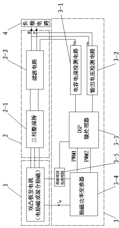
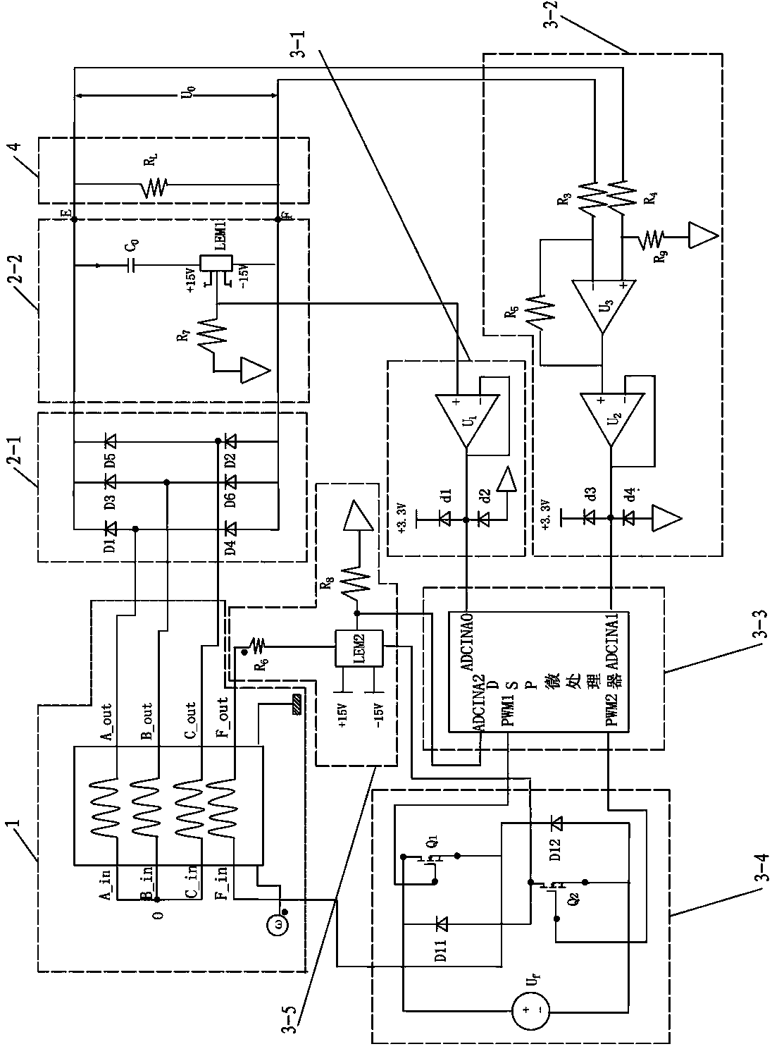
[0033] Such as figure 1 , 2 As shown, a doubly salient generator voltage regulating device includes a doubly salient generator 1, an AC-DC conversion circuit 2 and an excitation regulator 3,

[0034] a, the AC-DC conversion circuit 2 includes a three-phase rectifier bridge 2-1 and a filter circuit 2-2, the A, B, and C three-phase voltage output terminals of the double salient generator 1 are connected to the three-phase rectifier bridge 2 -1 is electrically connected to the input end, the output end of the three-phase rectifier bridge 2-1 is electrically connected to the input end of the filter circuit 2-2, and the filter circuit 2-2 has connection terminals E and F electrically connected to the load circuit 4;

[0035] b, the excitation regulator 3 includes a capacitive current detection circuit 3-1, an output voltag...


PUM


Abstract

The invention relates to a doubly salient generator voltage adjusting device. The doubly salient generator voltage adjusting device comprises a doubly salient generator, an alternating current and direct current converting circuit and an excitation regulator; the alternating current and direct current converting circuit and the excitation regulator are respectively connected with the doubly salient generator electrically; the alternating current and direct current converting circuit is electrically connected with the excitation regulator. The voltage controlling method comprises detecting output voltage of the doubly salient generator, constructing a sliding mode surface equation with output voltage deviation of the doubly salient generator and differential coefficients of the output voltage deviation serving as independent state variables, confirming values of a sliding mode coefficient, detecting the two state variables in real time and calculating a value of a sliding mode surface, controlling on and off of a corresponding switch tube in the excitation regulator and accordingly achieving purposes of adjusting the excitation currents and accordingly adjusting output voltage. The doubly salient generator voltage adjusting device and voltage controlling method thereof can overcome the disadvantage that the electricity generation performance of a generator system is reduced due to structural parameter variation after long-time operation and improves the generator dynamic response.

Description

technical field [0001] The invention specifically relates to a double salient generator voltage regulating device and a voltage regulating control method thereof. Background technique [0002] In the 1990s, the doubly salient motor proposed by Professor Lipo of the United States has been applied in many fields after years of research and development. The motor has a simple rotor structure, no windings on the rotor, no copper loss, and is suitable for high-speed operation, so it is more suitable for use as a high-speed generator. According to different excitation methods, the derivatives of doubly salient motors - electric excitation and hybrid excitation doubly salient motors, because of the existence of excitation windings, it is convenient to adjust the magnetic field of the motor, especially suitable for power generation applications. In addition, when the generator fails and the output voltage is too high, the generator can be demagnetized by cutting off the excitation ...

Claims


Application Information

Patent Timeline
Patent Type & Authority Applications(China)
IPC IPC(8): H02P9/14
Inventor 戴卫力丁骏田浩
Owner 智驱机电科技(常州)有限公司
Why Eureka
Try Eureka