Safety protection system of aircraft with multiple rotor wings

A multi-rotor aircraft, safety protection technology, applied in aircraft parts, parachutes, transportation and packaging, etc., can solve the problems of unable to maintain attitude, economic loss, propeller damage, etc., to avoid loss and personal injury, reduce its own weight, and apply wide range of effects

Inactive Publication Date: 2014-10-29
北京家晔科技有限公司
View PDF6 Cites 35 Cited by
  • Summary
  • Abstract
  • Description
  • Claims
  • Application Information

AI Technical Summary

Problems solved by technology

When the multi-rotor aircraft is flying, especially at low altitude, once the multi-rotor aircraft fails, such as the motor stops, the propeller is damaged, etc., the multi-rotor aircraft at this time can no longer maintain its stable attitude, and it will inevitably fall.
Since the multi-rotor aircraft often carries valuable equipment (such as a camera for aerial photography) on it when performing flight tasks, and the value of the multi-rotor aircraft itself is relatively expensive, so once a fall occurs, it will inevitably lead to the loss of valuable equipment. Damage to the equipment and the multi-rotor aircraft itself will cause large economic losses. At the same time, after the multi-rotor aircraft falls from a high altitude, it may also cause damage to personnel and other equipment on the ground
[0003] In today's technology, some operators also protect the multi-rotor aircraft by fixing parachutes on the multi-rotor aircraft, but in actual operation, since the parachute takes a certain time to open, if the multi-rotor aircraft fails when flying at low altitude, The multi-rotor aircraft will also fall due to the parachute not opening in time
Therefore, in the prior art, there is no mature and practical device or method to protect the multi-rotor aircraft in flight, especially low-altitude flight.

Method used


Image

  • Safety protection system of aircraft with multiple rotor wings
  • Safety protection system of aircraft with multiple rotor wings
  • Safety protection system of aircraft with multiple rotor wings

Examples


Embodiment 2

[0065] The difference between embodiment 2 and embodiment 1 is that the first controller in embodiment 2 is connected with multiple parachute pop-up devices in a wireless manner.

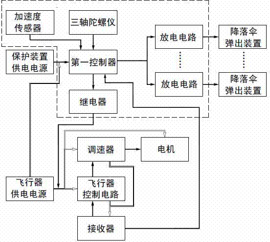
[0066] Such as Figure 12 As shown, in addition to being provided with an acceleration sensor, a three-axis gyroscope, a first controller and a relay, the safety device control circuit in Embodiment 2 is also provided with one or more wireless communication modules, which are realized through the first wireless communication module. Connection of the first controller to the parachute ejection device.

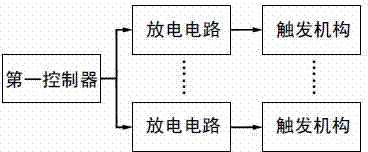
[0067] When the first controller is wirelessly connected with the parachute pop-up device 3 , a trigger device control circuit needs to be set to control the parachute pop-up device 3 . Such as Figure 13 As shown, the trigger device control circuit includes a second controller, a second wireless communication module, a discharge circuit and a power supply (not shown in the figure), and the power supp...

Embodiment 3

[0071] The difference between Embodiment 3 and Embodiment 1 is that, in the parachute ejection device 3 , the trigger mechanism 8 is omitted.

[0072] Such as Figure 14~15 As shown, the inside of the shell 7 is divided into a parachute cavity 6 above and a trigger cavity 10 below by a positioning plate 9 inside the shell 7 . Have some positioning plate air outlets 18 on the positioning plate 9, and the positioning plate air outlets 18 are sealed by wax under normal conditions. A parachute is inserted in the parachute cavity 6, and a second discharge electrode 17 is fixed in the trigger cavity 10. Same as Embodiment 1, an opening is provided at the bottom of the housing 7 , and the opening is blocked by a baffle 13 . Combustion agent is placed in the entire trigger chamber 10, and the wire 11 is connected to the second discharge electrode 17 through the opening on the side of the shell 7, and the opening on the side of the shell 7 can only allow the wire 11 to pass through. ...

Embodiment 4

[0074] Embodiment 4 differs from Embodiment 3 in that: in Embodiment 4, the bottom surface and one side of the parachute pop-up device 3 are closed, and the baffle plate 13 is arranged on the other side to block the parachute chamber 6 and the trigger chamber 10 from the side. The setting mode of positioning plate 9 is the same as that of embodiment 3. In this embodiment, the parachute pop-up device 3 is also detachably fixed on the inclined surface at the end of the fixed arm 4 .


PUM


Abstract

A safety protection system of an aircraft with multiple rotor wings comprises a receiver used for receiving ground remote control signals, an aircraft control circuit, a speed reducer, motors which are fixed at the ends of all rotary arms (1), and an aircraft power supply used for providing power for all above devices. The safety protection system of the aircraft with the multiple rotary wings is characterized in that a protection device control circuit, and a plurality of parachute popping-out devices (3) which are connected with the protection device control circuit and is controlled by the protection device control circuit to be triggered are arranged, after the parachute popping-out devices (3) are triggered, parachutes in the parachute popping-out devices are popped out, and protection to the multiple rotor wings is achieved. According to the safety protection system of the aircraft with the multiple rotor wings, the aircraft with the multiple rotor wings, which is in the flight process or in the low-altitude flight process, can be quickly and reliably protected, falling of the aircraft with the multiple rotor wings is prevented, and loss and personal injuries are avoided.

Description

technical field [0001] The invention relates to a multi-rotor aircraft safety protection system, which belongs to the field of multi-rotor aircraft safety equipment. Background technique [0002] Multi-rotor aircraft is a common unmanned aerial device. Due to its small size, reliable performance and high flexibility, it is widely used in various fields and can perform various flight tasks (such as aerial photography). When the multi-rotor aircraft is flying, especially at low altitude, once the multi-rotor aircraft breaks down, such as the motor stops, the propeller is damaged, etc., the multi-rotor aircraft at this time can no longer maintain its stable attitude, and it will inevitably fall. Since the multi-rotor aircraft often carries valuable equipment (such as a camera for aerial photography) on it when performing flight tasks, and the value of the multi-rotor aircraft itself is relatively expensive, so once a fall occurs, it will inevitably lead to the loss of valuable ...

Claims


Application Information

Patent Timeline
Patent Type & Authority Applications(China)
IPC IPC(8): B64D17/80B64D17/54
Inventor 张行晔张连宾
Owner 北京家晔科技有限公司
Why Eureka
Try Eureka