A miniature ultra-thin unidirectional rectifier bridge device and its processing technology

A rectifier bridge, ultra-thin technology, applied in the field of micro-ultra-thin unidirectional rectifier bridge devices and their processing technology, can solve the problems of increasing defect, reducing product reliability, reducing yield, etc., to reduce welding defect rate, improve Product reliability and cost reduction effects

Active Publication Date: 2017-04-05
颖拓萃半导体(南通)有限公司
View PDF4 Cites 0 Cited by
  • Summary
  • Abstract
  • Description
  • Claims
  • Application Information

AI Technical Summary

Problems solved by technology

At present, most of the micro rectifier bridge devices are still in the traditional pre-soldering process state. According to the existing rectifier bridge structure, the soldering defect rate is high and the product yield is low, which increases the cost and reduces the reliability of the product. wasted resources
The existing process uses pre-soldering, re-soldering, and secondary welding, which is inefficient, wastes manpower, and unstable in quality; at the same time, manual work needs to be shaken with a suction cup, causing chips to collide with each other, damaging the chip, and reducing the yield. It increases the potential badness and reduces the reliability; it is easy to cause missing chips during manual operation, which needs to be picked up with tweezers, which can easily cause damage to the chip and reduce the yield and reliability of the chip; the secondary soldering also damages the chip itself, increasing the The failure rate of the chip reduces the yield and reliability of the product

Method used


Image

  • A miniature ultra-thin unidirectional rectifier bridge device and its processing technology
  • A miniature ultra-thin unidirectional rectifier bridge device and its processing technology
  • A miniature ultra-thin unidirectional rectifier bridge device and its processing technology

Examples


Embodiment

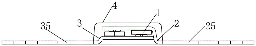
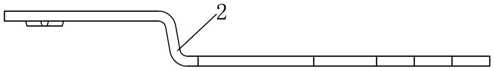
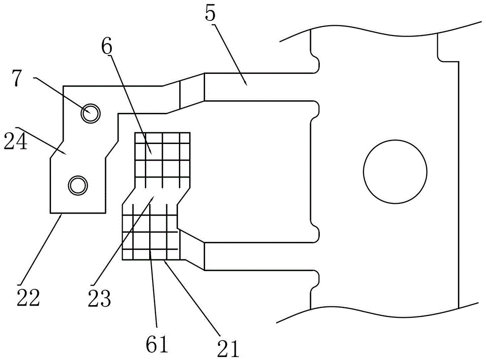
[0038] like Figure 1-8 As shown, a miniature ultra-thin unidirectional rectifier bridge device includes 4 rectifier chips 1 forming a rectifier bridge circuit, an upper material unit 2, a lower material unit 3 and a package body 4, and the rectifier chip 1 is arranged on the Between the above-mentioned upper material piece unit 2 and the described lower material piece unit 3, the described upper material piece unit 2 and the described lower material piece unit 3 are arranged oppositely, and the cross section is "Z" shape; the said upper material piece unit 2 and the lower material unit 3 both include two lead-out terminals 5, the lower surface of the lead-out terminal 5 is coplanar with the bottom surface of the package body 4; on the upper material unit 2 and the lower material unit 3 Both are provided with flat pads 6 and convex pads 7 with bumps. The upper material unit 2 protruding out of the package 4 forms an output terminal 25 , and the lower material unit 3 protrudin...


PUM


Abstract

The invention discloses a miniature ultrathin unidirectional rectifier bridge device which comprises four rectification chips for forming a rectifier bridge circuit, an upper sheet unit, a lower sheet unit and a packaging body. The rectification chips are arranged between the upper sheet unit and the lower sheet unit. The upper sheet unit is arranged opposite to the lower sheet unit, and the cross section of the upper sheet unit and the lower sheet unit is Z-shaped. The upper sheet unit and the lower sheet unit both comprises two leading-out terminals, the lower surfaces of which share the same plane with the bottom surface of the packaging body. The upper sheet unit and the lower sheet unit are both provided with a flat welding pad and a projection welding pad with bumps. Warps for promoting the upper sheet unit and the lower sheet unit to be combined with the rectification chips are arranged on the flat welding pad. By the miniature ultrathin unidirectional rectifier bridge device and its processing technology, through the arrangement of the warps on the flat welding pad and by man-made creation of sheet atoms for crystal orientation layout, sheets are welded with the chips more perfectly during the welding process due to crystal orientation effect of the two materials. Thus, welding reject rate is reduced, product reliability is raised, cost is decreased, and resources are saved.

Description

technical field [0001] The invention relates to a miniature semiconductor device, in particular to a miniature ultra-thin unidirectional rectifier bridge device and its processing technology. Background technique [0002] With the rapid development of science and technology, the popularization of product electronic modernization and the demand of the market, the society pays more attention to the reliability and low cost of products while pursuing practicality. At present, most of the micro rectifier bridge devices are still in the traditional pre-soldering process state. According to the existing rectifier bridge structure, the soldering defect rate is high and the product yield is low, which increases the cost and reduces the reliability of the product. Waste of resources. The existing process uses pre-soldering, re-soldering, and secondary welding, which is inefficient, wastes manpower, and unstable in quality; at the same time, manual work needs to be shaken with a suct...

Claims


Application Information

Patent Timeline
Patent Type & Authority Patents(China)
IPC IPC(8): H01L23/488H01L21/60
CPCH01L2224/16245
Inventor 王春飞陈海林邱立强
Owner 颖拓萃半导体(南通)有限公司
Why Eureka
Try Eureka