
Steel pipe column concrete lateral pouring method and steel pipe column structure used in method

A technology of concrete and steel pipe columns, which is applied in the field of steel pipe column structures, can solve the problems of low turnover efficiency and long time consumption, and achieve the effects of shortened pouring time, simple pouring, and shortened construction period

Inactive Publication Date: 2014-11-05
CHINA CONSTR FOURTH ENG DIV
View PDF4 Cites 7 Cited by
  • Summary
  • Abstract
  • Description
  • Claims
  • Application Information

AI Technical Summary

Problems solved by technology

[0005] 2. During pouring, the installation of the upper steel pipe columns, steel beams and profiled steel plates cannot be carried out, and the follow-up work can only be carried out after the pouring of the lower steel pipes is completed , affecting construction efficiency and delaying the construction period
[0006] 3. Since the profiled steel plate of the outer frame has not been laid during pouring, the distribution pipe is only fixed on the steel beam, the turnover efficiency is low and the time is too long

Method used


Image

  • Steel pipe column concrete lateral pouring method and steel pipe column structure used in method
  • Steel pipe column concrete lateral pouring method and steel pipe column structure used in method
  • Steel pipe column concrete lateral pouring method and steel pipe column structure used in method

Examples


Embodiment

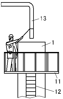
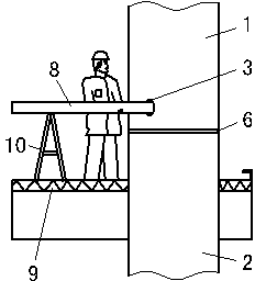
[0029] This example takes the R&F Yingkai Plaza project located in the core business district of Zhujiang New Town, Guangzhou as an example. The project has 5 floors underground and 65 floors above ground. It is a high-rise building with a frame-core tube structure, and the core tube is reinforced concrete shear force Wall structure, the outer cylinder structure is composed of 16 underground and 20 steel pipe concrete columns on the ground to form a side end support system. Pour 110mm thick concrete slab.

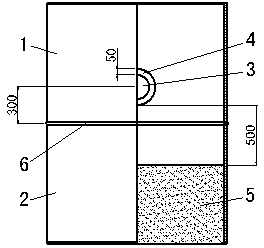
[0030] In this project, the supporting structure of steel pipe columns is used more, the height of steel pipe columns is high, and the engineering volume is large. In order to meet the requirements of the construction period, in this project, the pouring technology of traditional steel pipe column concrete (see figure 1 ) was innovated to use lateral pouring (see figure 2 )technology. This technology is to process a pouring hole 3 on the side wall of one end of ea...


PUM


Abstract

The invention discloses a steel pipe column concrete lateral pouring method and a steel pipe column structure used in the method. A steel pipe column is formed by welding multiple steel pipes. The method includes the steps that a pouring hole is formed in the side wall of the upper steel pipe, and then the upper steel pipe and the lower steel pipe are welded; when concrete in the lower steel pipe is poured, a concrete pumping pipe is inserted into the pouring hole in the upper steel pipe from the side face, and then pouring of the concrete in the lower steel pipe is finished. In the pouring process, construction of an upper-layer steel pipe column, a steel beam and a truss formwork is not influenced, synchronous construction can be achieved, work faces do not interfere with one another, installation efficiency of the steel structure is improved and the construction period is shortened. A worker can stand on an outer-frame horizontal beam and slab structure during pouring construction, safety risks are greatly reduced, pouring is easy and convenient to carry out, pouring can be carried out without a concrete spreader, operation time of the concrete spreader is saved, pouring time of the concrete of the steel pipe column is greatly shortened, the construction period is shortened, and labor expenses are reduced.

Description

technical field [0001] The invention relates to a side pouring method of steel pipe column concrete and a used steel pipe column structure, belonging to the technical field of steel pipe column pouring in building construction. Background technique [0002] In existing construction projects, due to the good load-bearing performance of the steel pipe column, the volume of the concrete column can be effectively reduced in the place where the force is greater, and it is more and more widely used in the vertical support of the engineering structure. Some steel pipe columns are taller and are usually welded from multiple steel pipes. Concrete is poured inside the steel pipe column. [0003] The method of pouring concrete in the prior art is to complete the pouring of concrete from the top of the steel pipe through the distributing pipe. There are following deficiencies: [0004] 1. In the construction of steel structures, the columns and beams are generally installed first and...

Claims


Application Information

Patent Timeline
Patent Type & Authority Applications(China)
IPC IPC(8): E04G21/02E04C3/36
Inventor 袁茂生袁成王皓刘丽丽梁森
Owner CHINA CONSTR FOURTH ENG DIV
Learn More