Operation mode analysis experiment method and device based on pulse excitation

A technology of pulse excitation and modal analysis, which is applied in the direction of measuring devices, testing of machines/structural components, instruments, etc., can solve the problems of cumbersome and difficult determination of the model order, and less response information

Active Publication Date: 2014-11-05
ZHEJIANG UNIV OF TECH
View PDF7 Cites 18 Cited by
  • Summary
  • Abstract
  • Description
  • Claims
  • Application Information

AI Technical Summary

Problems solved by technology

The parameter identification methods in operational modal analysis can be divided into time domain, frequency domain and time-frequency domain identification methods, etc., mainly including time series method, random decrement method (random decrement, RD), environmental excitation method, random subspace method , Empirical mode decomposition (empirical mode decomposition, EMD), peak picking method, frequency domain decomposition method and continuous wavelet transform method, etc., the existing analysis methods are mostly based on the assumption that the excitation signal is zero-mean white noise, and each method is There are certain limitations, for example, it is difficult to determine the model order of the time series method; the natural excitation method requires long data samples and many averag

Method used


Image

  • Operation mode analysis experiment method and device based on pulse excitation
  • Operation mode analysis experiment method and device based on pulse excitation
  • Operation mode analysis experiment method and device based on pulse excitation

Examples


Embodiment Construction

[0050] The present invention will be further described below in conjunction with the accompanying drawings.

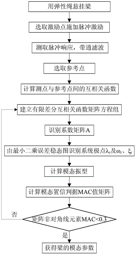
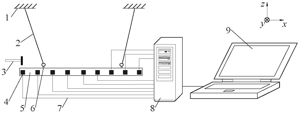
[0051] refer to Figure 1 to Figure 7 , a modal analysis method for spindle system operation based on multi-point pulse excitation, including the following steps:

[0052] 1) Select the end point of the beam as the excitation point, and use the steel hammer to implement pulse excitation on the beam;

[0053] Select the response point that is closer to the excitation point and has a larger response signal amplitude as the reference point;

[0054] Response measuring points are arranged at the reference point and each geometric model node reflecting the beam mode shape;

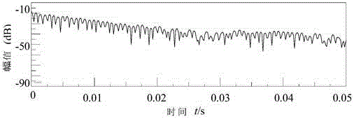
[0055] 2) collecting the response signals generated by the reference point and the response point after the pulse excitation;

[0056] 3) Band-pass filtering is performed on the collected signal, and the pass-band is the frequency range of the structural mode of interest;

[0057] 4) Obtain the cros...


PUM


Abstract

An operation mode analysis experiment method based on pulse excitation comprises the following steps: (1) the endpoint of a beam is chosen as an excitation point, and a steel hammer is used to implement pulse excitation on the beam; (2) response signals generated by a reference point and a response point after pulse excitation are acquired; (3) band-pass filtering is performed on the acquired signals; (5) a cross-correlation function between the reference point and the response point is obtained, and a matrix equation set composed of data at different sampling moments of time of the cross-correlation function is constructed; (5) a coefficient matrix is solved by using the matrix equation set; (6) a system pole is identified, a least square error stabilization graph is established, and a modal shape is solved; and (7) if the modal assurance criterion value is poor, the value at a different sampling moment of time is selected, and the method returns to step (4) until the modal assurance criterion value is within a preset reasonable interval, and the modal parameters of the beam are obtained. The invention further provides an operation mode analysis experiment device based on pulse excitation. The time and the intensity of test can be reduced, and the students' learning effect can be improved.

Description

technical field [0001] The invention relates to the technical field of operation mode analysis, in particular to an operation mode analysis experiment method and device. Background technique [0002] In the teaching process of engineering testing technology, mechanical vibration and other courses, adding some modal analysis experiments can stimulate students' interest in learning, mobilize students' learning enthusiasm and initiative, cultivate students' innovative ability, and greatly improve the teaching effect. Through experiments, students can gain rich perceptual knowledge, deepen students' understanding of obscure physical concepts, theorems and laws, and reduce the difficulty of students encountering problems in the process of self-study; with the help of experiments, they can explain problems vividly, concretely and intuitively, and be able to Make abstract knowledge come alive quickly. [0003] The existing experimental modal analysis system generally consists of t...

Claims


Application Information

Patent Timeline
IPC IPC(8): G01M7/02G01H17/00
Inventor 王慧强王扬渝文东辉蔡东海陈恒
Owner ZHEJIANG UNIV OF TECH
Why Eureka
Try Eureka