Plasma-mig welding method and welding torch

A welding method and plasma welding technology, applied in the directions of plasma welding equipment, plasma, welding equipment, etc., can solve the problem of reducing the amount of spatter, and achieve the effect of reducing the amount of spatter

Inactive Publication Date: 2014-11-05
HONDA MOTOR CO LTD
View PDF4 Cites 6 Cited by
  • Summary
  • Abstract
  • Description
  • Claims
  • Application Information

AI Technical Summary

Problems solved by technology

However, there is a limit to the effect of reducing the amount of spatter by controlling the MIG welding power source

Method used


Image

  • Plasma-mig welding method and welding torch
  • Plasma-mig welding method and welding torch
  • Plasma-mig welding method and welding torch

Examples


Embodiment

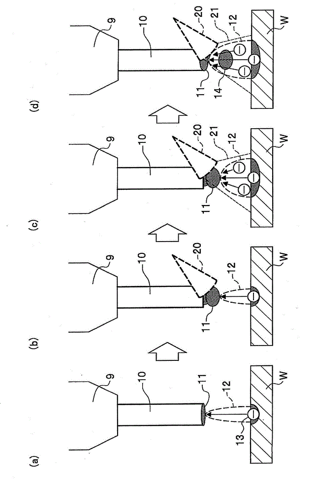
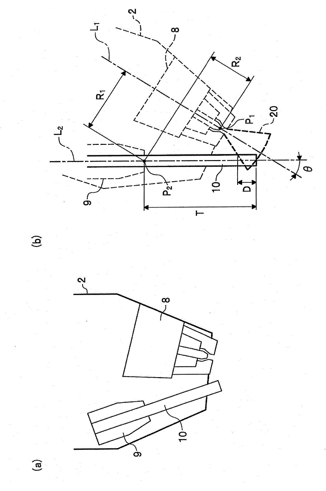
[0082]As the effect of the plasma-MIG welding method of the present invention, by using plasma to heat the MIG welding wire, the droplet can be dispersed in the air without short-circuit transfer, and the droplet transfer can be carried out. In order to confirm this effect, the plasma welding The torch part 8 and the MIG welding torch 9 were arranged at a predetermined distance apart from each other in different directions, and the following experiments 1 and 2 were performed.

[0083] The conditions common to each experiment are as follows. The MIG welding current (also referred to simply as MIG current) was a constant value (150A). The diameter of the welding wire is 1 mm.


PUM

PropertyMeasurementUnit
sizeaaaaaaaaaa
diameteraaaaaaaaaa

Abstract

Provided are a plasma-MIG welding method and a welding torch that are capable of reducing spatter amount without relying on control of the MIG welding power supply. The plasma-MIG welding method employs a plasma-MIG welding device configured from: a plasma torch section that includes a plasma nozzle and a plasma electrode; and an MIG torch (9) that includes an MIG tip and a welding wire (10). The plasma torch section and the MIG torch (9) are arranged so as to face in different directions at a predetermined distance from one another. The plasma-MIG welding method is characterized in that a plasma arc (21) is made to overlap locally with the tip portion of the welding wire (10) in order to carry out heating, and in a state in which melting of the welding wire (10) has been promoted, MIG welding is carried out without short-circuiting between a workpiece (W) and the tip (11) of the welding wire (10), said welding wire (10) being a consumable electrode.

Description

technical field [0001] The invention relates to a technique for assisting consumable electrode type welding by plasma, in particular to a plasma-MIG welding method and a welding torch. Background technique [0002] Conventionally, a MIG welding method (metal inert gas welding) is known. Such as Figure 6 As shown, a typical conventional MIG torch includes a MIG tip 101 , a welding wire 102 passing through the tip, and a protective nozzle 103 . Then, for example, an arc (MIG arc) 104 is generated by supplying electric power from an unillustrated MIG welding power source as a DC power source to a welding wire 102 as a consumable electrode via a MIG tip 101 for power supply. At this time, a shielding gas 105 such as argon is supplied between the MIG tip 101 and the shielding nozzle 103 . Such as Figure 6 As shown, the central axes of the MIG tip 101 and the guard nozzle 103 coincide (coaxially), and the tip sides of the MIG tip 101 and the guard nozzle 103 face the surface o...

Claims


Application Information

Patent Timeline
Patent Type & Authority Applications(China)
IPC IPC(8): B23K9/16B23K9/173B23K10/00B23K10/02B23K28/02
CPCB23K9/295B23K9/173B23K10/02H05H1/34
Inventor 村松祐辅松本克也北川纯濑户田启志
Owner HONDA MOTOR CO LTD
Why Eureka
Try Eureka