Wireless communication system and radio frequency device

A wireless communication system and radio frequency technology, applied in the field of wireless communication systems and radio frequency devices, can solve problems such as low system reliability and RRU inoperability, and achieve the effect of improving reliability

Active Publication Date: 2014-11-05
HUAWEI TECH CO LTD
View PDF5 Cites 0 Cited by
  • Summary
  • Abstract
  • Description
  • Claims
  • Application Information

AI Technical Summary

Problems solved by technology

[0007] In view of this, the embodiment of the present invention provides a wireless communication system and a wireless radio frequency device, which solves the problem that in the exis...

Method used


Image

  • Wireless communication system and radio frequency device
  • Wireless communication system and radio frequency device
  • Wireless communication system and radio frequency device

Examples


Embodiment 1

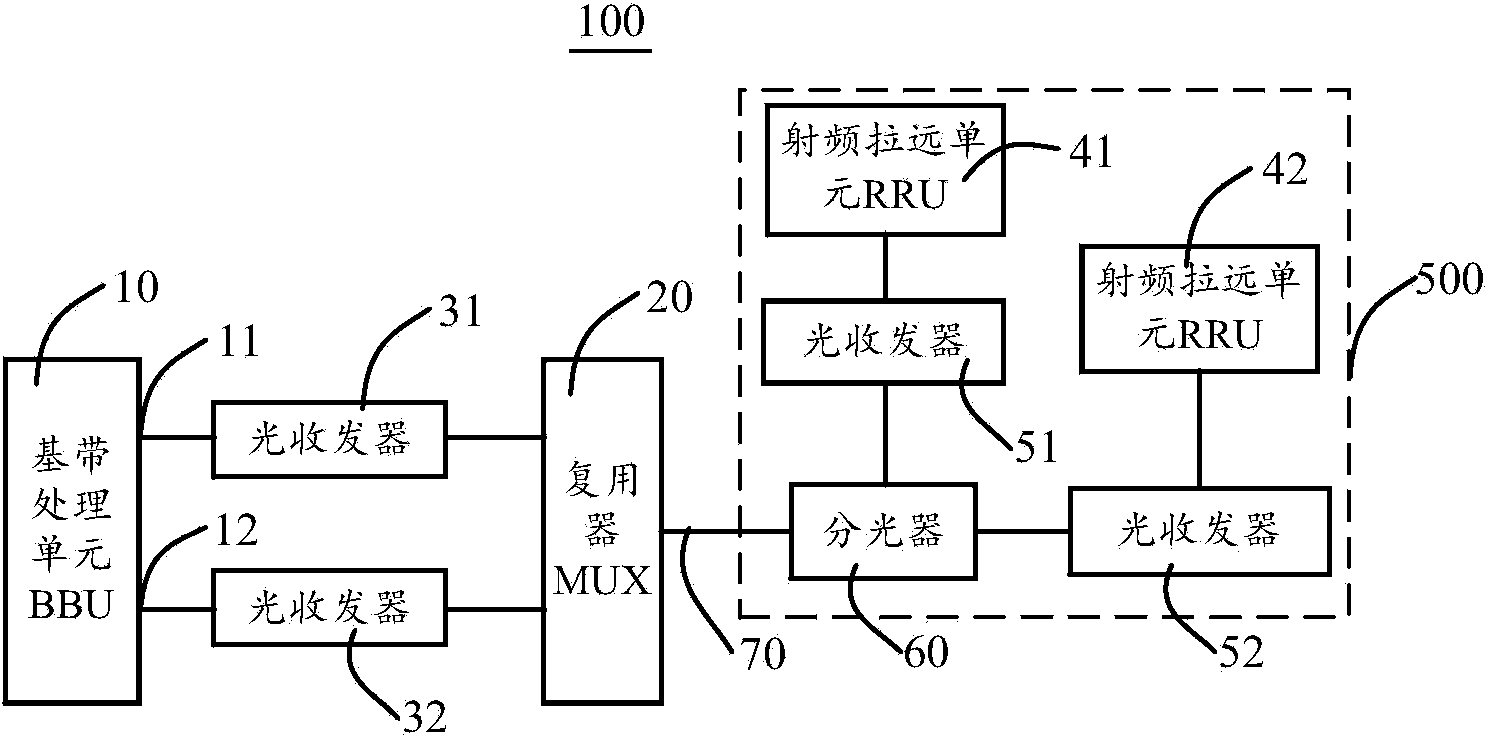
[0036] figure 1 A schematic structural diagram of a wireless communication system 100 provided by an embodiment of the present invention. like figure 1 As shown, the wireless communication system 100 includes: a baseband processing unit 10, an optical multiplexer 20, optical transceivers 31 and 32, and a wireless radio frequency device 500, and the wireless radio frequency device 500 includes radio remote units 41 and 42, optical transceivers 51 and 52 and beam splitter 60.

[0037] The baseband processing unit 10, referred to as BBU, is called Baseband Control Unit in full, and is also called a baseband control unit. The BBU 10 may include a transmission subsystem, a baseband subsystem, a control subsystem, and a power supply module. The transmission subsystem is used to realize the function of data transmission and reception, including the interface between the BBU and the core network / controller and the interface between the BBU and the radio frequency module. The inte...

Embodiment 2

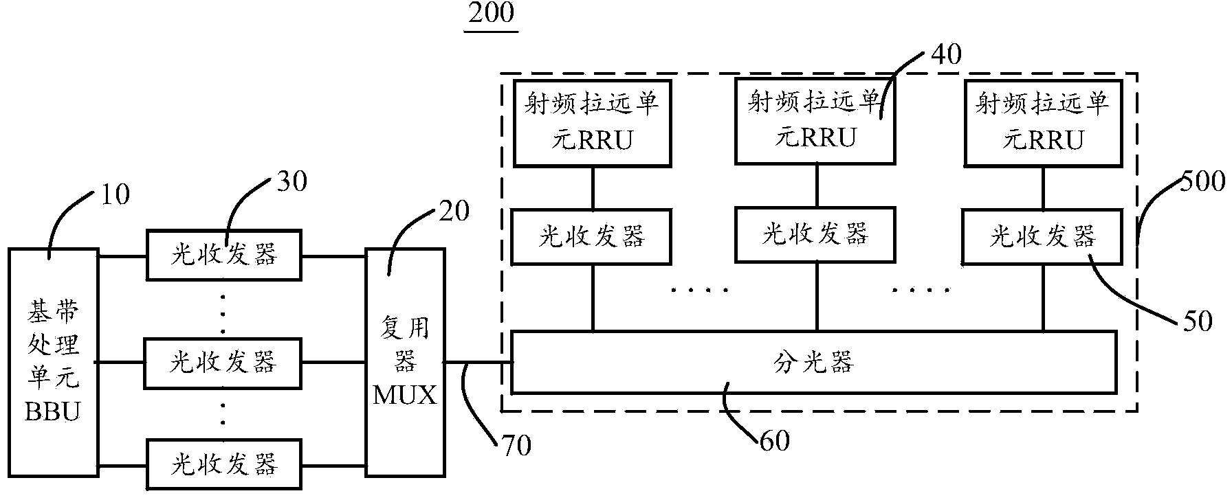
[0057] Based on the same inventive concept, the present application also provides a wireless communication system 200 . like figure 2 As shown, the difference between the wireless communication system 200 and the wireless communication system 100 lies in: the number of optical transceivers, the number of RRUs are different, and the optical splitters are different.

[0058] In this embodiment, the number of RRUs 40 is M. Correspondingly, M optical transceivers 50 are respectively connected to M RRUs 40, and M interfaces between the BBU 10 and M RRUs 40 are provided with M an optical transceiver 30. The optical splitter 60 may be a 1:N optical splitter, wherein M is an integer greater than or equal to 3, and N is an integer greater than or equal to 2. The M RRUs 40 are respectively connected to the optical splitter 60 through the M optical transceivers 50 .

[0059] In this embodiment, the N is equal to M, and the optical splitter 60 is a 1:M optical splitter with M+1 interf...

Embodiment 3

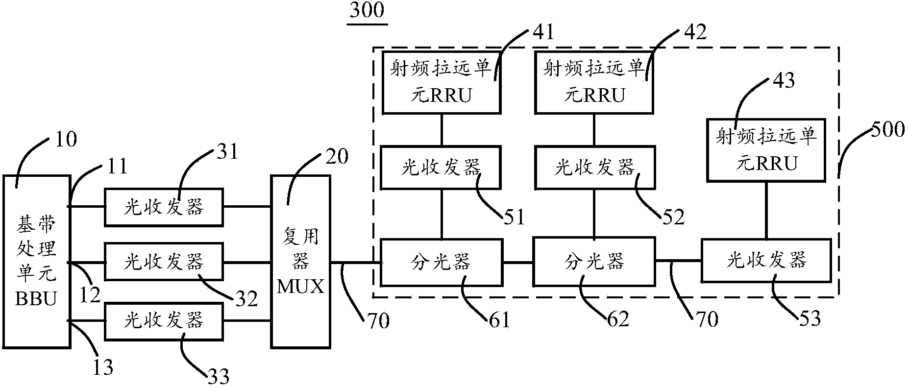
[0064] Based on the same inventive concept, the present application also provides a wireless communication system 300 . like image 3 As shown, it is a schematic structural diagram of a wireless communication system 300 provided by another embodiment of the present invention. The wireless communication system 300 and figure 1 The difference of the wireless communication system 100 in the above is that the number of optical splitters 60 is two, the number of RRU 40 is three, correspondingly, the number of interfaces of BBU 10 is also three, and the number of optical transceivers 30 connected to BBU 10 is The number of optical transceivers 50 connected to the RRU 40 is also three.

[0065] The number of optical splitters 60 is one less than the number of RRUs 40 , namely two optical transceivers 61 and 62 . Wherein, the optical splitter 61 is connected to the optical multiplexer 20 and the optical splitter 62, the RRU 41 is connected to the optical splitter 61 through the op...


PUM


Abstract

The invention embodiment discloses a wireless communication system and a radio frequency device; the wireless communication system comprises the following structures: a baseband processing unit, an optical multiplexer, M first optical transceivers and a radio frequency device; the M first optical transceivers are arranged between the baseband processing unit and the optical multiplexer; work wavelengths of the M first optical transceivers are different, and the M is an integer bigger than 2; the radio frequcny device comprises M radio remote units, M second optical transceivers and at least one optical spliter; the M second optical transceivers are respectively connected with the M radio remote units and matched with the M first optical transceivers, and work wavelengths of the matched first and second optical transceivers are matched; the M second optical transceivers are connected with one fiber through the at least one optical spliter, and the fiber is connected with either the optical multiplexer or the optical splitter.

Description

technical field [0001] The present invention relates to the technical field of communication, in particular to a wireless communication system and a wireless radio frequency device. Background technique [0002] A large number of wireless networks use a distributed base station architecture. The remote radio unit (Remote Radio Unit, RRU) and the baseband processing unit (Baseband Control Unit, BBU) are connected by optical fiber, and one BBU can support multiple RRUs. In the scenario where multiple RRUs need to be connected to the same BBU at the same site, cascading multiple RRUs is a common networking method. [0003] The data transmission method of the wireless communication system 900 in which one BBU supports two cascaded RRUs is taken as an example to illustrate: Figure 5 As shown, in the downlink direction, the BBU 90 receives the downlink data sent by the gateway, processes the downlink data, and sends the processed downlink data to the optical transceiver (optical ...

Claims


Application Information

Patent Timeline
IPC IPC(8): H04J14/02H04B7/26
CPCH04J14/02H04J14/0201H04B10/11H04B10/40H04B10/2575G02B6/2938
Inventor 冯烈训
Owner HUAWEI TECH CO LTD
Why Eureka
Try Eureka