An automatic control system for core components of a mass spectrometer

A technology of mass spectrometer and optical system, which is applied in the field of optical system for automatic control of laser analysis spot of mass spectrometer, can solve the problems of controlling the size of laser spot and difficulty in adapting to the needs of application targets, and achieve the effect of enhancing the actual use function

Inactive Publication Date: 2017-09-01
许洋
View PDF10 Cites 0 Cited by
  • Summary
  • Abstract
  • Description
  • Claims
  • Application Information

AI Technical Summary

Problems solved by technology

[0006] However, the conventional mass spectrometer laser optical focusing system can only transform the laser beam into a specific laser spot size, and it is difficult to dynamically control the actual laser spot size according to the needs of use, making it difficult to adapt to the needs of different application targets

Method used


Image

  • An automatic control system for core components of a mass spectrometer
  • An automatic control system for core components of a mass spectrometer

Examples


specific Embodiment approach

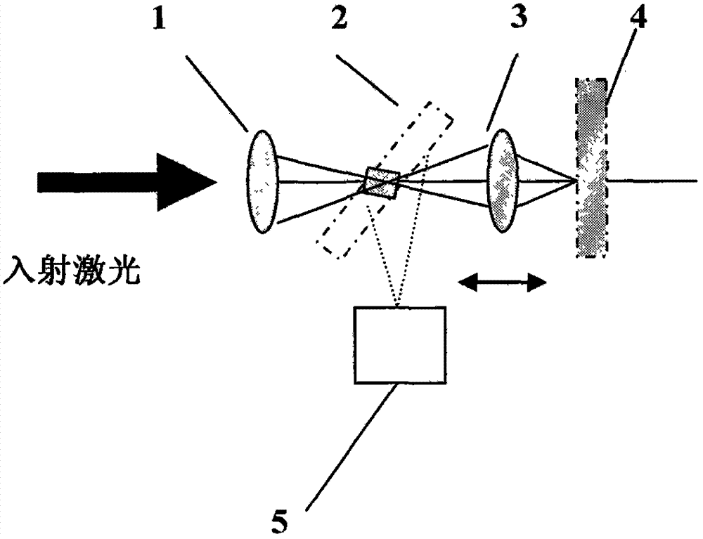
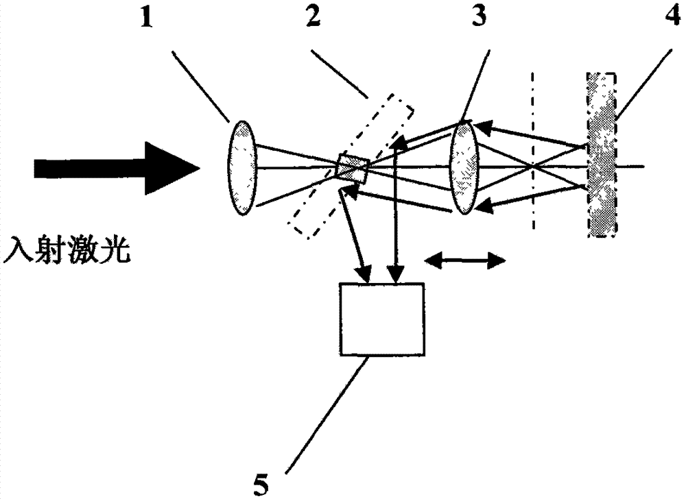
[0013] Such as figure 1 and figure 2 As shown, an optical system for automatic control of the laser analysis spot size of a mass spectrometer consists of an incident lens 1, a mirror 2 with a central transmission hole, a relay lens 3, a correction mirror 4 and a photodetector 5. The incident lens 1, the reflector 2 with the central transmission hole, the relay lens 3 and the correction reflector 4 are arranged in sequence in space, the reflector 2 with the central transmission hole is placed at 45 degrees to the optical axis of the incident laser, and the photodetector 5 placed in the vertical direction of the incident laser optical axis. The incident lens 1 focuses the incident laser light to the central hole position of the reflective mirror 2 with the central transmission hole and makes it pass through the reflective mirror 2 with the central hole, and the relay lens 3 will focus and emit from the reflective mirror 2 with the central transmission hole The laser light is ...


PUM


Abstract

The invention discloses an optical system for automatically controlling the size of the laser analysis mode spot of a mass spectrometer, which is composed of an incident lens, a reflection mirror with a central transmission hole, a relay lens, a correction reflection mirror and a photoelectric detector. The incident lens, the mirror with the central transmission hole, the relay lens and the correction mirror are arranged sequentially in space, the mirror with the central transmission hole is placed at 45 degrees to the optical axis of the incident laser light, and the photodetector is placed at the center of the incident laser light The vertical direction of the axis. According to the laser power received by the photodetector, the laser spot size of the incident laser beam incident on the correction mirror is determined. By moving the relay lens and changing the distance between the relay lens and the correction mirror, the size of the laser spot incident on the correction mirror is dynamically adjusted. The invention provides an automatic control optical system capable of dynamically controlling the size of the analytical laser spot. By controlling the size of the laser analytical spot, the requirements of the mass spectrometer under different test conditions are met, and the working performance of the mass spectrometer is enhanced.

Description

technical field [0001] The invention relates to an optical system for controlling a laser spot, in particular to an optical system for automatic control of a laser analysis spot of a mass spectrometer. Background technique [0002] As a high-end analytical instrument, mass spectrometer has extremely important application value in the fields of biomedicine and material analysis. Mass spectrometers based on laser desorption ion sources mainly use short-wavelength ultraviolet pulse lasers as laser sources for ion desorption. [0003] At present, the production and research of protein flight mass spectrometers used for the prevention and detection of human diseases often use a nitrogen laser with a wavelength of 337nm as the analytical laser source. Due to the beam quality of the nitrogen laser, the laser spot size is relatively large when the mass spectrometer is working, and precise spot size control is actually difficult to achieve. [0004] With the development of all-soli...

Claims


Application Information

Patent Timeline
Patent Type & Authority Patents(China)
IPC IPC(8): H01J49/02G02B27/48
Inventor 许洋沈永行姜培培
Owner 许洋
Why Eureka
Try Eureka