
Honey extractor

A honey throwing machine and barrel technology, which is applied in honey collection, application, beekeeping and other directions, can solve the problems of polluted honey, very labor-intensive, honey waste, etc., and achieves the effect of improving efficiency, reducing residue and small resistance.

Inactive Publication Date: 2014-11-19
SUQIAN WANGSHI BEE PARK
View PDF0 Cites 3 Cited by
  • Summary
  • Abstract
  • Description
  • Claims
  • Application Information

AI Technical Summary

Problems solved by technology

The operator of this method of throwing honey needs to rotate quickly, which takes a lot of energy and is also not conducive to industrial production.
The honey of the current honey shaker is discharged from the side wall, and the collection is not complete, resulting in waste of honey, and the honey remains in the honey shaker, which is not easy to clean. When the honey shaker is used again, the residual honey inside will pollute the new shaker. out of honey

Method used


Image

  • Honey extractor
  • Honey extractor
  • Honey extractor

Examples


Embodiment Construction

[0017] The present invention will be further explained below in conjunction with the accompanying drawings and specific embodiments. It should be understood that the following specific embodiments are only used to illustrate the present invention but not to limit the scope of the present invention.

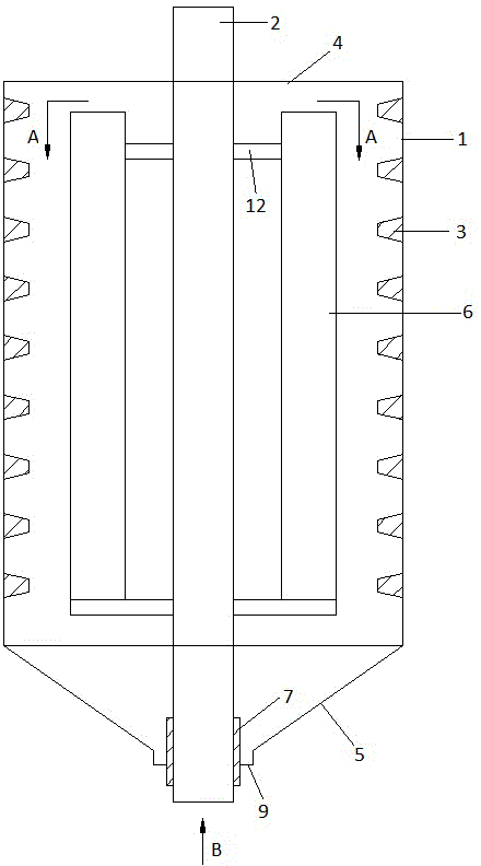
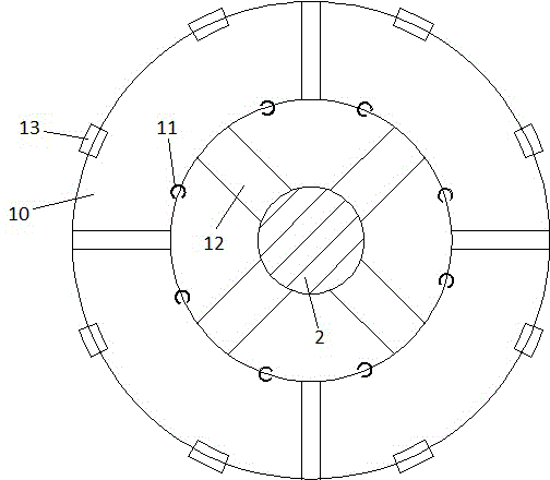
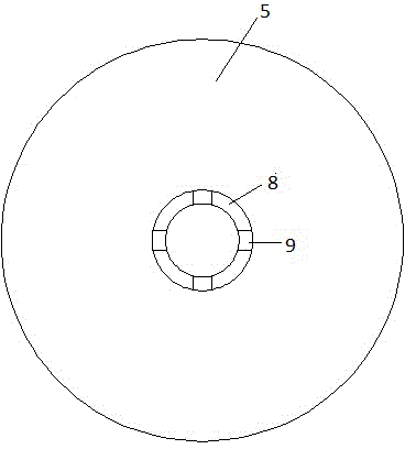
[0018] figure 1 It is a schematic diagram of the structure of the present invention. It can be seen from the figure that in the present invention, the center of the barrel body 1 is provided with a rotating shaft 2, and the inner wall of the barrel body 1 is provided with a spirally inclined convex thread 3. The convex thread 3 is a trapezoidal thread, and the top of the barrel body 1 is provided with There is a cover 4, the bottom of the barrel body 1 is provided with a back cover 5, the top and bottom ends of the rotating shaft 2 extend out of the cover 4 and the bottom cover 5 respectively, and a honeycomb holder 6 is arranged around the rotating shaft 2, and the rotating shaft...


PUM


Abstract

Disclosed is a honey extractor which comprises a barrel. A rotating shaft is arranged at the center of the barrel, a spiral oblique convex thread is arranged on the inner wall of the barrel, a close cover is arranged at the top of the barrel, a back cover is arranged at the bottom of the barrel, the top end and the bottom end of the rotating shaft respectively extend out of the close cover and the back cover, honeycomb holders are arranged on the periphery of the rotating shaft, a bearing is arranged on the periphery of the rotating shaft and fixed to the bottom cover through a plurality of fixing and connecting plates, the bottom cover is conical, and a gap between every two adjacent fixing and connecting plates is a honey outlet. The honeycomb holders are two concentric round tubes formed by coiling of steel wire meshes, the bottoms of the concentric round tubes are connected via the steel wire meshes, and a plurality of flip covers of rotary switches are arranged between the tops of the concentric round tubes. The honey extractor is high in honey extraction efficiency, honey residual in honeycombs as well as in the barrel is less, and honey is fully discharged from the honey outlets.

Description

technical field [0001] The invention relates to a honey throwing machine, which is a device for separating honey in a honeycomb and belongs to mechanical equipment for beekeeping. Background technique [0002] The traditional method of throwing honey is to manually shake out the honey in the hive and collect the honey. This separation method is inefficient. During the process of throwing out the honey, the honey is easy to splash out, resulting in waste of honey and pollution of environmental sanitation. , is not conducive to industrial production. [0003] At present, there is a hand-cranked honey shaker on the market. After the honeycomb is installed and fixed in the honey shaker, the handle is selected and shaken, the honeycomb rotates in the honey shaker, and the honey in the honeycomb is thrown out by using the inertial force. The operator of such method of throwing honey needs to rotate rapidly, takes a lot of physical effort, and is unfavorable for suitability for i...

Claims


Application Information

Patent Timeline
IPC IPC(8): A01K59/00
Inventor 王安兵
Owner SUQIAN WANGSHI BEE PARK
Learn More