Glass fiber bin with feed control system

A feed control, glass fiber technology, applied in the field of silo, can solve the problems of liquid level temperature effect, powder agglomeration, silo damage, etc., to prevent the influence of liquid level and temperature, simple structure, and ensure safety production effect

Inactive Publication Date: 2014-11-19
TAIJIA GLASS FIBER
View PDF7 Cites 2 Cited by
  • Summary
  • Abstract
  • Description
  • Claims
  • Application Information

AI Technical Summary

Problems solved by technology

[0005] However, the functions that the structure of the currently used silos can provide are only limited to the simple processes of feeding, storing and delivering materials.
In the process of use, we found that, on the one hand, because the materials, especially the glass fiber powder in the process of glass fiber processing, due to their fine particles, basically around 200 mesh, they are similar to flowing water when they flow downward. Similarly, the flow rate is fast, and when it goes straight down from the silo to the next container for processing, if it enters the kiln, it is very easy to cause a large amount of flushing, which will cause liquid level and other damage to the kiln equipment. The impact on the temperature will affect the production of the next process; on the other hand, the powder stored in the silo for a long time is very easy to agglomerate due to its strong molecular force, so it takes a long time to discharge the material. Only a large vibration force can make it loose, and a large vibration force will inevitably cause damage to the entire silo and affect the service life of the silo

Method used


Image

  • Glass fiber bin with feed control system
  • Glass fiber bin with feed control system
  • Glass fiber bin with feed control system

Examples


Embodiment 1

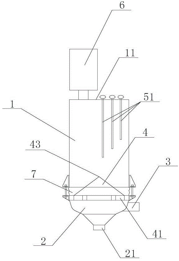
[0035] This embodiment is the most preferred for implementing the present invention. Such as Figure 1-2 As shown, in this example the

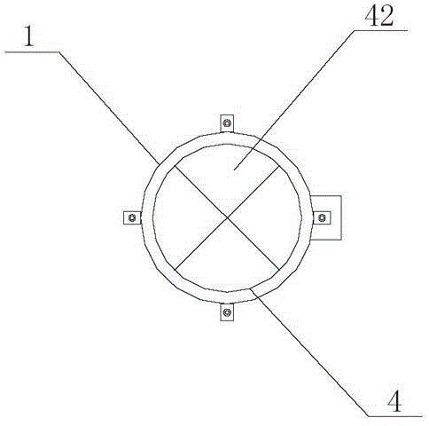
[0036] A glass fiber silo with a feed control system includes: a silo part 1; a feeding part 2, which is fixedly connected to the bottom of the silo part 1, and the fixed connection method can be a known fixed connection such as screw connection or welding. In the same way, the blanking part 2 is also provided with a discharge port 21; the tapered part 4, which is arranged in the blanking part 2, is fixedly connected with the inner wall of the blanking part 2, and the fixed connection method can also be screwed. , welding and other known fixed connection methods, the conical top 43 of the conical part 4 is set up against the feed port 11 of the silo part 1, between the bottom periphery of the conical part 4 and the inner wall of the blanking part 2 There is a gap for the material to pass through. When feeding material from the silo part 1 ...

Embodiment 2

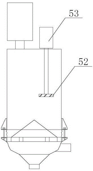
[0049] Others are the same as those described in Embodiment 1, the difference is: as image 3 As shown, the above-mentioned material level sensing group includes an impeller 52 and a motor 53, the impeller 52 is arranged in the silo part 1, the rotating shaft of the motor 53 is fixedly connected to the impeller 52, and is used to drive the impeller 52 to rotate in the silo part, The motor 52 is also electrically connected to an industrial computer (not shown), and the industrial computer is electrically connected to an alarm (not shown), for when the motor 52 is running, the industrial computer sends an alarm command to the alarm, and the alarm alarm. The working process is: when there is material, the impeller cannot rotate due to the pressure of the material. If the material fed into the silo is not in place, the impeller will run with the rotation of the motor, and the motor will send a corresponding electrical signal to the industrial computer. The industrial computer con...

Embodiment 3

[0051] Others are the same as those described in Embodiment 1 or 2, except that the tapered portion 4 is arranged in the silo portion 1 and is fixedly connected with the inner wall of the silo portion 1, and the bottom of the tapered portion 4 is connected with the There is a gap for material to pass between the inner walls of the silo part 1 . The tapered part 4 can also be centrally arranged in the bin part 1 . The support frame 41 can be fixedly connected with the inner wall of the bin part 1 . This setting is also similar to the effect achieved in Embodiment 1, and the user can choose to install it as needed.


PUM


Abstract

The invention discloses a glass fiber bin with a feed control system. The glass fiber bin comprises a bin portion, a discharging portion fixedly connected to the bottom of the bin portion and a conical portion arranged in the discharging portion or the bin portion and fixedly connected with the inner wall of the discharging portion or the inner wall of the bin portion. The conical vertex of the conical portion right faces the feed port of the bin portion, and a gap for materials to pass through is reserved between the bottom periphery of the conical portion and the inner wall of the discharging portion or the inner wall of the bin portion. According to the glass fiber bin, the material rushing phenomenon can be eliminated, the next process production can be guaranteed, the caking phenomenon can be eliminated, and therefore the bin can be prevented from being damaged.

Description

[0001] technical field [0002] The invention relates to a silo, in particular to a glass fiber silo with a feeding control system. [0003] Background technique [0004] The silo is a kind of equipment used for conveying materials such as pellets, powders, flakes and strips. It has a wide range of applications, especially in today's society, more and more industries are beginning to have mechanized The feeding method replaces the traditional manual feeding method, which improves production efficiency and reduces labor intensity while gaining convenience. Therefore, the silo can be said to be an important equipment that is widely welcomed and widely used by everyone. [0005] But, the function that its structure can provide of the currently used silo is only limited to simple feeding, storage and feeding these operations. In the process of use, we found that, on the one hand, because the materials, especially the glass fiber powder in the glass fiber processing process, d...

Claims


Application Information

Patent Timeline
Patent Type & Authority Applications(China)
IPC IPC(8): B65D90/48B65D90/02B65D90/00
Inventor 林嘉佑
Owner TAIJIA GLASS FIBER
Why Eureka
Try Eureka