
Microporous heat insulation board with high anti-radiation rate and low heat conductivity coefficient and preparation method thereof

A thermal insulation board and microporous technology, applied in the field of thermal insulation, can solve the problems such as the use of thermal insulation boards for high radiation infrared energy-saving coatings that have not yet been seen, and achieve the effects of reducing liquid metal crusts, good thermal insulation performance, and convenient on-site construction and dismantling.

Active Publication Date: 2014-11-19
瑞吉斯昇态链(天津)咨询有限公司
View PDF2 Cites 7 Cited by
  • Summary
  • Abstract
  • Description
  • Claims
  • Application Information

AI Technical Summary

Problems solved by technology

At present, there is no report on the use of high-radiation infrared energy-saving coatings on thermal insulation panels

Method used

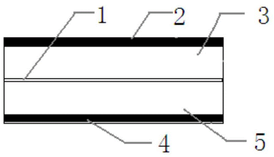

Image

  • Microporous heat insulation board with high anti-radiation rate and low heat conductivity coefficient and preparation method thereof
  • Microporous heat insulation board with high anti-radiation rate and low heat conductivity coefficient and preparation method thereof
  • Microporous heat insulation board with high anti-radiation rate and low heat conductivity coefficient and preparation method thereof

Examples


Embodiment 1

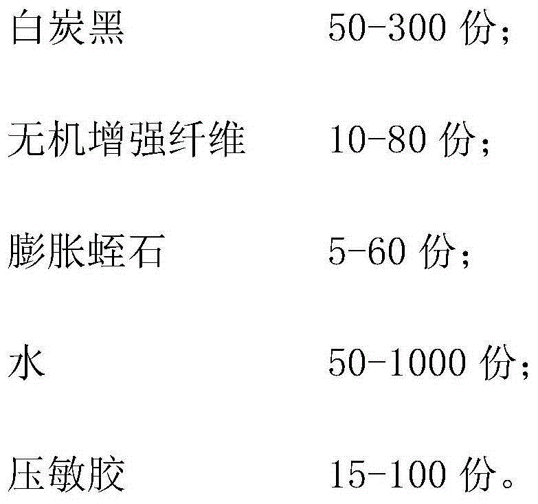
[0042] (1) Prepare pressure-sensitive adhesive solution: weigh 72g of pressure-sensitive adhesive in 680g of water, and mix evenly;

[0043] (2) Weigh 200g of fumed silica, 50g of expanded vermiculite, and 18g of glass fibers are mixed uniformly;

[0044] (3) After mixing the weighed pressure-sensitive adhesive solution in the steel basin evenly, add the mixed solid powder, stir evenly, and obtain the heat insulating material;

[0045] (4) Apply the thermal insulation material in step (3) on the fiber mesh cloth with aluminum foil on the plate, and scrape it flat, with a thickness of about 2-3mm.

[0046] (5) Cover the upper part with a layer of high-temperature-resistant fiber mesh cloth as a reinforcing rib, and then coat a layer of heat-insulating material with a thickness of about 2 to 3 mm, and press and form it.

[0047] (6) Put the above products in a small oven to dry part of the water, control the drying temperature not to exceed 230°C, and then use a needle board de...

Embodiment 2

[0060] (1) Prepare pressure-sensitive adhesive solution: weigh 72g of pressure-sensitive adhesive in 680g of water, and mix evenly;

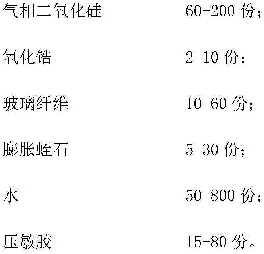
[0061] (2) Weigh fumed silica 200g, zirconia 5g, expanded vermiculite 20g, glass fiber 18g and mix uniformly;

[0062] (3) After mixing the weighed pressure-sensitive adhesive solution in the steel basin evenly, add the mixed solid powder, stir evenly, and obtain the heat insulating material;

[0063] (4) Apply the thermal insulation material in step (3) on the fiber mesh cloth with aluminum foil on the plate, and scrape it flat, with a thickness of about 2-3mm.

[0064] (5) Cover the upper part with a layer of high-temperature-resistant fiber mesh cloth as a reinforcing rib, and then coat a layer of heat-insulating material with a thickness of about 2 to 3 mm, and press and form it.

[0065] (6) After drying part of the water in a small oven, the needles are punched to facilitate the evaporation of water.

[0066] (7) After drying, spray a la...


PUM

PropertyMeasurementUnit
Compressive strengthaaaaaaaaaa
Flexural strengthaaaaaaaaaa
Thermal conductivityaaaaaaaaaa

Abstract

The invention provides a microporous heat insulation board with a high anti-radiation rate and a low heat conductivity coefficient and a preparation method thereof. The microporous heat insulation board takes white carbon black, an infrared light-screening agent and expanded vermiculite as main heat insulation materials, wherein added inorganic reinforced fibers are taken as a reinforcing material, pressure-sensitive adhesive is taken as a main binding material, high temperature-resistant glass fiber grid cloth as a reinforcing rib for a sandwich layer and a high-temperature radiant infrared energy-saving material is sprayed on the surface of the reinforcing rib; the microporous heat insulation board has excellent characteristics of ultralow thermal capacity, ultralow thermal conductivity, good flexibility, bendability, and easiness in constructing, cutting and processing.

Description

technical field [0001] The invention belongs to the technical field of heat insulation, and in particular relates to a microporous heat insulation board with high radiation reflection rate and low thermal conductivity and a preparation method thereof. Background technique [0002] In recent years, with the rapid development of nanotechnology, the traditional macroscopic heat transfer has been impacted, and an emerging technical field of microscopic heat transfer has been formed internationally. The research on the theory and application of micro-nano scale heat transfer has been actively carried out to provide new thermal insulation materials. Materials and energy-saving and consumption-reducing technologies have opened up a new way. Microporous insulation board is far ahead among various materials with its extremely low thermal conductivity and stable performance. Compared with traditional thermal insulation panels, microporous thermal insulation panels have ultra-low heat...

Claims


Application Information

Patent Timeline
IPC IPC(8): C04B35/66
Inventor 李振声宋伟张旭王轩
Owner 瑞吉斯昇态链(天津)咨询有限公司
Learn More