
A method for manufacturing high temperature resistant bundled optical fibers

A manufacturing method and high-temperature-resistant technology, applied in the direction of superimposed layer plating, metal material coating process, coating, etc., can solve problems such as inability to apply high-temperature detection, and achieve wide application of optical fiber measurement, large transmission information capacity, and transmission fast effect

Active Publication Date: 2017-04-05
NANCHANG UNIV
View PDF4 Cites 0 Cited by
  • Summary
  • Abstract
  • Description
  • Claims
  • Application Information

AI Technical Summary

Problems solved by technology

At present, bundled optical fibers protected by cladding such as organic plastics have been used as sensing probes, but plastic cladding and organic cladding cannot be used for high-temperature detection
At present, there are no relevant reports on the use of electroless plating combined with electroplating to make bundled optical fibers

Method used


Image

  • A method for manufacturing high temperature resistant bundled optical fibers
  • A method for manufacturing high temperature resistant bundled optical fibers
  • A method for manufacturing high temperature resistant bundled optical fibers

Examples


Embodiment 1

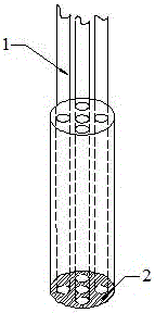
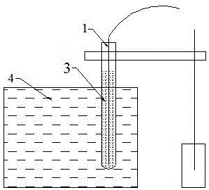
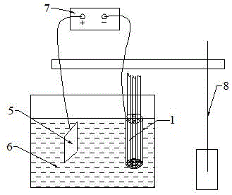
[0026] Embodiment 1: Get 3 optical fibers, according to the formula of sensitization solution (SnCl 2 2H 2 O is 10g / L; HCl is 40ml / L), activation solution formula (PdCl 2 0.5g / L; HCl is 5ml / L) to prepare sensitizing solution and activation solution respectively, and activate them after sensitization at a temperature of 25°C for 15min and 20min respectively, and then according to the formula of electroless copper plating solution (CuSO 4 ·5H 2 O is 10g / L; NaKC 4 h 4 o 6 ·5H 2 O is 40g / L; NaCO 3 2g / L; NiCl 2 ·H 2 O is 1g / L; HCHO is 20ml / L; NaOH is 10g / L) prepare electroless copper plating solution, carry out electroless copper plating when temperature is 25 ℃, time is 4h, as figure 2 As shown, the thickness of the coating is 4 μm, and the length of the electroless coating is 150 mm. Then according to the electroplating solution formula (CuSO 4 250g / L; glucose 40g / L; H 2 SO 4 70g / L) to prepare an electroplating copper solution, tightly bundle the chemically plated o...

Embodiment 2

[0027] Embodiment 2: Get 5 optical fibers, press the sensitizing solution formula (SnCl 2 2H 2 O is 10g / L; HCl is 40ml / L), activation solution formula (PdCl 2 0.5g / L; HCl is 5ml / L) to prepare sensitizing solution and activation solution respectively, and activate them after sensitization at a temperature of 25°C for 15min and 20min respectively, and then according to the formula of electroless copper plating solution (CuSO 4 ·5H 2 O is 10g / L; NaKC 4 h 4 o 6 ·5H 2 O is 40g / L; NaCO 3 2g / L; NiCl 2 ·H 2 O is 1g / L; HCHO is 20ml / L; NaOH is 10g / L) prepare electroless copper plating solution, carry out electroless copper plating when temperature is 25 ℃, the time is 5h, as figure 2 As shown, the thickness of the coating is 6 μm, and the length of the electroless coating is 200 mm. Then according to the electroplating solution formula (CuSO 4 250g / L; glucose 40g / L; H 2 SO 4 70g / L) to prepare an electroplating copper solution, tightly bundle the chemically plated optical f...

Embodiment 3

[0028] Embodiment 3: get 8 optical fibers, press the formula of sensitization solution (SnCl 2 2H 2O is 10g / L; HCl is 40ml / L), activation solution formula (PdCl 2 0.5g / L; HCl is 5ml / L) to prepare sensitizing solution and activation solution respectively, and activate them after sensitization at a temperature of 25°C for 15min and 20min respectively, and then according to the formula of electroless copper plating solution (CuSO 4 ·5H 2 O is 10g / L; NaKC 4 h 4 o 6 ·5H 2 O is 40g / L; NaCO 3 2g / L; NiCl 2 ·H 2 O is 1g / L; HCHO is 20ml / L; NaOH is 10g / L) prepare electroless copper plating solution, carry out electroless copper plating when temperature is 25 ℃, the time is 6h, as figure 2 As shown, the thickness of the coating is 8 μm, and the length of the electroless coating is 250 mm. Then according to the electroplating solution formula (CuSO 4 250g / L; glucose 40g / L; H 2 SO 4 70g / L) to prepare an electroplating copper solution, tightly bundle the chemically plated optic...


PUM

PropertyMeasurementUnit
thicknessaaaaaaaaaa
lengthaaaaaaaaaa
lengthaaaaaaaaaa

Abstract

The invention provides a manufacturing method for high-temperature resistant bundling optical fibers. The manufacturing method for high-temperature resistant bundling optical fibers comprises the following steps: a plurality of common optical fibers are taken; surface sensitization treatment and surface activation treatment are conducted on the common optical fibers respectively; then, a chemical plating is conducted; the thickness of a clad layer is 4-8 micron; the length that the clad layer protects is 150-250 mm; chemically plated optical fibers are tied into a bundle by adopting thin strings; the end parts of the chemically plated optical fibers are in parallel and level; the bundle of chemically plated optical fibers is placed into an electroplating liquid for electroplating, so that all the optical fibers are enabled to be tightly combined and optical fiber bundles are formed; the diameter of the entire bundling optical fibers is 0.5-1 mm; the length that the electroplating clad layer protects is 100-200 mm. According to the manufacturing method for the high-temperature resistant bundling optical fibers, through conducting surface metallization on the common optical fibers, the plurality of optical fibers are made into the bundling optical fibers; the bundling optical fibers have the advantages of low probability of damages, high-temperature resistance, high transmission information capacity and the like; the multiple bundling optical fibers are wrapped with a sensing probe, so as to form a multi-channel transmitting bundling optical fibers; the information transmission capacity is large; the manufacturing method for the high-temperature resistant bundling optical fibers can be used for fields of simultaneous distinction and measurement of multiple physical quantities, or a detection probe of the bundling optical fibers and the like.

Description

technical field [0001] The invention relates to the technical field of optical fiber applications, in particular to a method for manufacturing high-temperature-resistant bundled optical fibers. Background technique [0002] As a new type of sensing element, optical fiber has the advantages of good light guiding performance, low loss, anti-electromagnetic interference, good insulation, small size, light weight, etc. It is widely used in various industrial fields, especially in the field of sensing . Fiber-based sensors have many characteristics, such as high sensitivity, fast transmission speed, large information capacity, and wide applicability. Optical fiber sensors have been widely used in the detection of parameters such as temperature and pressure in harsh environments such as civil engineering and aerospace. With the development of modern industry, the performance requirements for optical fiber sensors are getting higher and higher, especially for high temperature res...

Claims


Application Information

Patent Timeline
Patent Type & Authority Patents(China)
IPC IPC(8): C23C28/02
Inventor 李玉龙江建锋温昌金
Owner NANCHANG UNIV
Learn More