Intelligent control system for spun yarn forming

An intelligent control system, spinning technology, applied in textiles and papermaking, etc., can solve problems such as inaccurate position

Active Publication Date: 2014-11-19
YIBIN HUIMEI WORSTED TECH +1
View PDF5 Cites 6 Cited by
  • Summary
  • Abstract
  • Description
  • Claims
  • Application Information

AI Technical Summary

Problems solved by technology

[0010] In order to overcome the defect that the existing spinning machine can not control the action of the ring plate accurately, the present invention provides an intelligent control system for spun yarn forming. The intelligent control system can accurately detect whether the ring plate has accurately reached the initial The yarn position, pull-back position and the highest position ensure that each action is accurate and overcome the defects caused by inaccurate positions

Method used


Image

  • Intelligent control system for spun yarn forming
  • Intelligent control system for spun yarn forming

Examples


Embodiment 1

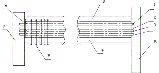
[0030] In this embodiment, a position sensor 6 is installed in the initial position 4, the pull-back position 3, and the highest position 1 that need to be reached by the guide plate of the existing spinning frame to detect whether the ring plate is accurately in place, and the ring plate guides the yarn Wind on the bobbin 5. Such as figure 1 As shown, the head 7, tail 10, upper beam 8, and lower beam 9 of the spinning frame constitute four positions of the ring plate movement, and these four positions are located between the upper beam 8 and the lower beam 9.

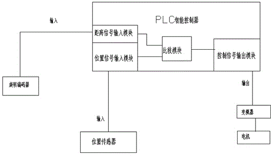
[0031] Such as figure 2 As shown, the present invention requires a rotary encoder, a PLC intelligent controller, a frequency converter, and a motor. The rotary encoder is used to calculate the rising and falling distance of the ring plate, and transmit the calculated distance signal to the PLC intelligent controller, which is controlled by the PLC The controller also needs to receive the position signals transmitted by ...

Embodiment 2

[0038] This embodiment includes a signal acquisition unit, a control unit, and an execution unit; the signal acquisition unit is used to collect signals on whether the ring plate has reached the initial position, the middle yarn position, the retract position, and the highest position. The control unit uses After receiving the signal collected by the signal collection unit, the collected signal is compared with the set signal and then the control signal is outputted. The execution unit is used to receive the control signal output by the control unit, and to determine according to the received control signal Control the rise and fall of the ring plate.

[0039] The signal acquisition unit includes a position sensor and a rotary encoder. There are three sensors, which are installed in the initial position, the retracted position, and the highest position respectively. The position sensor and the rotary encoder are both connected to the control unit. The position sensor is used In o...


PUM


Abstract

The invention relates to an intelligent control system for spun yarn forming. The intelligent control system comprises a signal acquisition unit, a control unit and an execution unit. The signal acquisition unit is used for collecting signals indicating whether a steel collar plate reaches an initial position, a yarn middle pull position, a pullback position and the highest position; the control unit is used for receiving the signals collected by the signal acquisition unit and outputting control signals after the collected signals are compared with set signals and judged; the execution unit is used for receiving the control signals output by the control unit and controlling ascending and descending of the steel collar plate according to the received control signals. According to the intelligent control system, whether the steel collar plate reaches the initial position, the yarn middle pull position, the pullback position and the highest position accurately can be precisely detected, it is guaranteed that each movement is precisely in place, and the defects brought by inaccurate positions are overcome.

Description

Technical field [0001] The invention relates to a spinning frame for yarn production, in particular to a forming control system of the spinning frame. Background technique [0002] The production unit of the spinning frame is the spindle, and the production level of the spinning frame is often measured by the output per thousand spindle hours (kg). The production scale of a spinning mill is expressed in terms of the total number of spindles with spinning frames. The yarn spun on each spindle will break due to various reasons, and the rate of end breakage is often expressed in terms of the number of ends per thousand spindles. The level of end breakage affects labor productivity, equipment productivity, spun yarn quality and workshop dust content. The spinning frame is the most energy-consuming machine in spinning production. During the production process of the spinning frame, the production of a full package (bob) must be stopped, and the spinning can be continued after the b...

Claims


Application Information

Patent Timeline
Patent Type & Authority Applications(China)
IPC IPC(8): D01H13/32D01H7/52
Inventor 赵茂宇宛小红
Owner YIBIN HUIMEI WORSTED TECH
Why Eureka
Try Eureka