A reducer output shaft lengthening device

A technology of reducer and output shaft, which is applied in the direction of transmission, transmission parts, mechanical equipment, etc., can solve the problems of cost increase, failure to meet the use requirements, and the length of the output shaft of the standard reducer is not long enough, so as to increase the length and save energy. Go to costly effect

Active Publication Date: 2016-05-25
时代试金(山东)科学仪器有限公司
View PDF7 Cites 0 Cited by
  • Summary
  • Abstract
  • Description
  • Claims
  • Application Information

AI Technical Summary

Problems solved by technology

In practical applications, considering various factors of mechanical equipment, the length of the output shaft of the optional standard reducer is not long enough to meet the requirements of use, and special customization will lead to a great increase in cost

Method used


Image

  • A reducer output shaft lengthening device
  • A reducer output shaft lengthening device
  • A reducer output shaft lengthening device

Examples


Embodiment Construction

[0013] The present invention will be described in further detail below in conjunction with the accompanying drawings.

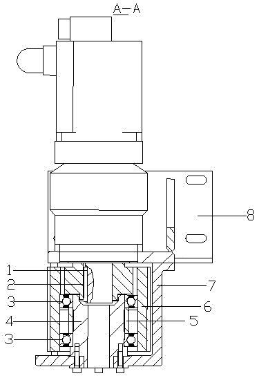
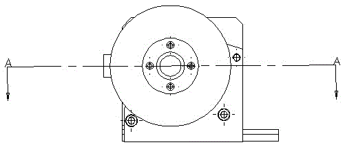
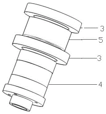
[0014] Such as Figure 1-3 , a testing machine output shaft extension structure, including a reducer output shaft 1, a drive pulley 6 fixed outside the reducer output shaft 1 through a flat key 2, and an elongated structure positioned below the reducer output shaft 1, the drive pulley 6 It is a hollow cylindrical structure divided into upper and lower parts, the inner diameter of the upper part is smaller than the inner diameter of the lower part, the output shaft 1 of the reducer is located in the upper part of the transmission pulley, and the extension structure is located in the lower part of the transmission pulley; the extension structure includes The extension shaft 4, Two deep groove ball bearings 3 sleeved outside the extension shaft 4 and a sleeve 5 sleeved outside the extension shaft 4 and between the two deep groove ball bearings 3, the two ends of...


PUM


Abstract

The invention provides a speed reducer output shaft lengthening device which comprises a speed reducer output shaft 1, a transmission belt pulley 6 fixed to the outer side of the speed reducer output shaft 1 through a flat key 2, and a lengthening structure located on the lower face of the speed reducer output shaft 1. The lengthening structure comprises a lengthening shaft 4, two deep groove ball bearings 3 arranged outside the lengthening shaft 4 in a sleeved mode, and a sleeve 5 arranged outside the lengthening shaft 4 in a sleeved mode and located between the two deep groove ball bearings 3. The two ends of the sleeve 5 abut against the inner circles of the deep groove ball bearings 3. The lengthening structure is fixed into the lower portion of the transmission belt pulley 6 through the outer circles of the deep groove ball bearings 3. A cylindrical speed reducer support 7 is arranged outside the transmission belt pulley 6 and connected with the lower end of the lengthening shaft 4. The lengthening structure composed of the lengthening shaft 4, the sleeve 5 and the deep groove ball bearings 3 is added, and therefore the length of the speed reducer output shaft 1 is increased, the actual use requirements are met, and high cost for special customization is saved.

Description

technical field [0001] The invention relates to a lengthening device for a mechanical transmission system, in particular to a lengthening device for an output shaft of a reducer. Background technique [0002] The reducer is widely used in the driving part of mechanical equipment due to its characteristics of large reduction ratio, high precision, high rigidity and high load capacity. The output shaft of the reducer is an important part connected with mechanical equipment. The diameter and length of the output shaft of the reducer are important reference data for the design of the drive pulley. In practical applications, considering various factors of mechanical equipment, the length of the output shaft of the optional standard reducer is not long enough to meet the requirements of use, and special customization will lead to a significant increase in cost. Contents of the invention [0003] Aiming at the defects of the prior art, the technical problem to be solved by the p...

Claims


Application Information

Patent Timeline
Patent Type & Authority Patents(China)
IPC IPC(8): F16H7/02F16H57/00
CPCF16H57/0018F16H57/0025
Inventor 楚万慧吴洪晓王健葛云燕
Owner 时代试金(山东)科学仪器有限公司
Why Eureka
Try Eureka