Centralized air-conditioner exhausted-air heat/cold energy recovery system

A recovery system and centralized technology, applied in the field of energy saving of air conditioning systems, can solve the problems of increasing energy consumption of units, affecting comfort, and expensive heat exchangers, improving heat dissipation in summer and cooling in winter, and improving refrigeration and production. Improved thermal efficiency and overall energy saving effect

Inactive Publication Date: 2014-11-19
CHANGSHA UNIVERSITY OF SCIENCE AND TECHNOLOGY
View PDF5 Cites 3 Cited by
  • Summary
  • Abstract
  • Description
  • Claims
  • Application Information

AI Technical Summary

Problems solved by technology

However, there are many disadvantages in this heat recovery method: first, a large heat transfer temperature difference is required on both sides of the partition heat exchanger, otherwise the heat transfer effect is not good and the heat recovery rate is low; second, the heat exchanger is expensive and the initial investment Or the transformation cost is high; again, there is air leakage in the heat exchanger, and this heat recovery method is not allowed in places where cross-infection needs to be prevented, such as in infectious wards
There are mainly the following problems in adopting this measure: first, during the defrosting cycle, the indoor temperature drops, which affects the comfort; second, the defrosting cycle consumes extra electric energy and increases the energy consumption of the unit; third, the switching action of heating and cooling in winter Frequent, loud noise, easy wear and tear of equipment, affecting the life of the unit

Method used


Image

  • Centralized air-conditioner exhausted-air heat/cold energy recovery system

Examples


Embodiment Construction

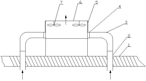
[0009] In order to facilitate construction and installation and reduce the length of connecting pipes, the system of the present invention should generally be arranged on the roof, such as figure 1 Shown: including roof 1, exhaust pipe 2, exhaust air guide pipe 3, exhaust air inlet 4, unit air inlet 5, air-cooled heat pump unit 6 and fan 7. Wherein the outlet end 2 of the exhaust pipe is connected with the inlet end of the exhaust air guide pipe 3 , and the outlet end of the exhaust air guide pipe 3 is connected with the exhaust air inlet 4 . Exhaust air heat (cold) recovery system has introduced left and right two exhaust air ducts 3. The exhaust air inlet 4 is located directly below the air inlet 5 of the unit, and is drawn out by 30 cm for introducing the exhaust air into the heat pump unit. The exhaust air guide pipe 3 is a circular air duct, and its insulation material is polyurethane foam with a thickness of 25 millimeters, and one deck of aluminum foil protective layer...


PUM


Abstract

The invention relates to a centralized air-conditioner exhausted-air heat/cold energy recovery system. The system aims to recover heat/cold energy of exhausted air of an air conditioner and prevent an air-cooled heat pump unit from frosting in winter so as to improve the unit efficiency and the comprehensive energy-saving effect of the air conditioner. By means of the heat/cold energy recovery system, the air exhausted by the air conditioner is introduced into an air inlet end of the air-cooled heat pump unit directly. The feature of an air conditioner system that the exhausted-air temperature is lower than the outdoor temperature in summer, the exhausted-air temperature is higher than the outdoor temperature in winter is adopted, the exhausted air is introduced into the air inlet end of the air-cooled unit, the effects of heat dissipation in summer and cold dissipation in winder of the heat pump unit are improved greatly, the refrigeration efficiency and heating efficiency of the unit are improved, and energy consumption is saved; meanwhile, the hot air exhausted from a room in winter can prevent the heat pump unit from frosting effectively, the defrosting energy consumption of the unit is saved, and comfort in the room in winter is improved. Furthermore, only a connection air pipe needs to be additionally arranged on the heat energy recovery device, and the investment is saved greatly compared with a conventional heat recovery mode of using a heat exchanger.

Description

technical field [0001] The invention relates to the technical field of energy-saving of air-conditioning systems, in particular to an exhaust heat (cooling capacity) recovery system of a centralized air-conditioning system using an air-cooled heat pump unit as a cold and heat source. Background technique [0002] With the improvement of people's living standards, the application of centralized air conditioners (that is, central air conditioners) is becoming more and more extensive, and its energy consumption is also increasing. Using technical means to save energy consumption of air conditioners is a very important way to save energy. At present, for small and medium-sized centralized air-conditioning systems that require cooling in summer and heating in winter, air-cooled heat pump units are generally used as cold and heat sources. With the improvement of people's requirements for indoor air quality, fresh air volume and corresponding exhaust The air volume generally incre...

Claims


Application Information

Patent Timeline
Patent Type & Authority Applications(China)
IPC IPC(8): F24F12/00
CPCY02P80/15
Inventor 黄永红王成赵永青
Owner CHANGSHA UNIVERSITY OF SCIENCE AND TECHNOLOGY
Why Eureka
Try Eureka