Multi-stage evaporation micro-channel heat pipe heat transferring and radiating device

A technology of micro-channel heat pipe and heat dissipation device, which is applied in indirect heat exchangers, lighting and heating equipment, etc., can solve the problems of affecting the working performance of heat pipes, reducing heat transfer efficiency, drying of capillary structure, etc., and achieving excellent isothermal performance and temperature. controllability, increase the heat extraction area, and reduce the effect of thermal coupling

Inactive Publication Date: 2014-11-19
UNIV OF ELECTRONICS SCI & TECH OF CHINA
View PDF9 Cites 9 Cited by
  • Summary
  • Abstract
  • Description
  • Claims
  • Application Information

AI Technical Summary

Problems solved by technology

In recent years, flat heat pipes have been used in heat dissipation industries such as LEDs. However, when dissipating heat from multiple heat sources with different powers, the evaporation ends between the heat sources are connected in series. Usually, one heat sink absorbs multiple heat sources. There may be thermal coupling between each heat source, and the power loss per unit volume is very large, and the operating temperature of each heating electronic component may be different, so it is difficult to achieve uniform temperature, and local and overall thermal failure and thermal degradation will occur. At the same time After the flat heat pipe absorbs the heat emitted by high-power electronic components, the working medium in the capillary structure on the lower plate evaporates to take away the heat. At this time, if the capillary structure is too thick, the reaction time for the working medium to evaporate is long, and the heat transfer efficiency is not good. High; if the capillary structure is too thin, the capillary structure is prone to drying or even burning, which will affect the working performance of the heat pipe
If the steam or the liquid returned by capillary action travels too far, the resistance will increase sharply, which may lead to signs of dryness at the evaporation end and reduce heat transfer efficiency

Method used


Image

  • Multi-stage evaporation micro-channel heat pipe heat transferring and radiating device
  • Multi-stage evaporation micro-channel heat pipe heat transferring and radiating device
  • Multi-stage evaporation micro-channel heat pipe heat transferring and radiating device

Examples


Embodiment 1

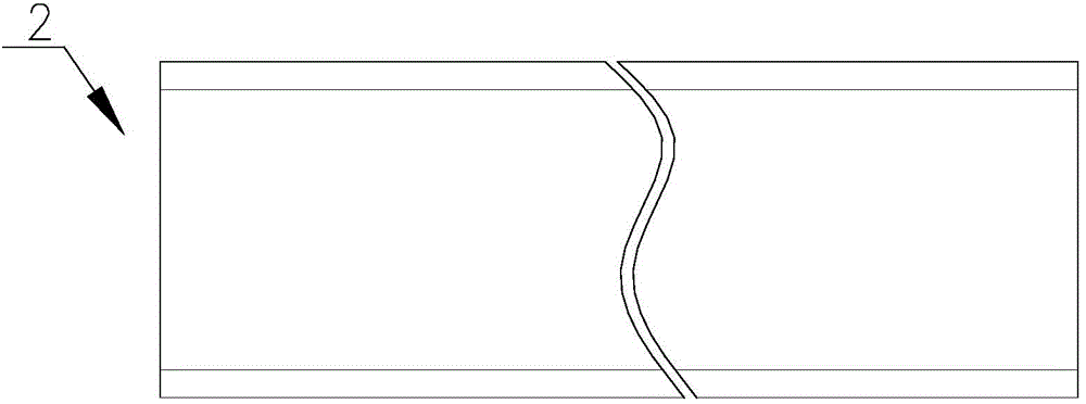
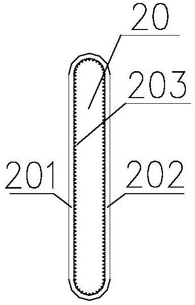
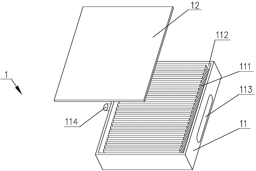
[0029] The heat dissipation device in this example is a two-stage evaporative heat transfer system, including two independent working fluid circulation systems composed of a heat absorption end and a heat dissipation end. In this example, the heat sink is composed of three heat sinks 1, which are respectively installed on the three heat sources. Each heat sink 1 is connected to the condenser 3 through a heat pipe 2, such as Figure 4 shown. The size of each heat sink 1 (indicating the number of microchannels included) is determined by the calorific value and heating area of ​​the heat source. The larger the heat source, the larger the installed heat sink and the more microchannels it contains. Figure 5 The microchannel structure inside the condenser 3 is shown. According to the size of the three connected heat sinks 1, the condenser 3 in this example is divided into three parts of corresponding size, each part includes a number of microchannels 311, and the The number corre...

Embodiment 2

[0032] In the heat sink of this example, a heat transfer device is connected between the heat absorption end and the heat dissipation end. The structure of the heat transfer device is as follows: Figure 9 As shown, the condenser end 33 and the evaporation end 31 are included. The condenser end 33 and the evaporation end 31 have the same structure as the condenser 3. The microchannel structure inside the condenser end 33 and the evaporation end 31 can be referred to the structure of the condenser 3, which is also divided into three parts. Parts are connected by three heat pipes 2 to form three enclosed and independent working fluid circulation spaces, such as Figure 9 Shown in dashed line. The heat transfer device in this example also uses the phase change of the working medium to transfer heat. The connection structure between the transfer device and the heat absorption end and the heat dissipation end is as follows Figure 10 As shown, the evaporation end 31 is welded with...


PUM


Abstract

The invention relates to a radiating device and discloses a multi-stage evaporation micro-channel heat pipe heat transferring and radiating device. The device comprises two independent working medium circulating systems, and each working medium circulating system is composed of a heat absorbing end and a radiating end; each heat absorbing end comprises at least one heat sink, each heat sink is connected with a condenser through a heat pipe, the condenser is correspondingly divided into several parts according to the number of the heat sinks connected with the condenser, and each part of the condenser and the corresponding heat pipe and the corresponding heat sink connected with the part of the condenser form a sealed independent working medium circulating space; each radiating end comprises an evaporator and a radiator, each evaporator is connected with the corresponding radiator to absorb heat and transfer the heat to the corresponding radiator through the corresponding heat pipe, each evaporator is the same as the condenser in structure, and the condenser, the evaporators and the radiators are provided with micro-channel structures. The heat sinks connected with heat sources and corresponding working medium circulating spaces are independent, a thermal coupling function is reduced, and by means of two-stage evaporation, heat conduction capacity can be greatly improved and flow resistance of fluids in the heat pipes can be greatly reduced.

Description

technical field [0001] The invention relates to a heat dissipation device, in particular to a device that combines microchannels and heat pipes and adopts multi-stage evaporation to dissipate heat from multiple heat sources. Background technique [0002] Since the 1970s, countries have begun to research and develop multi-chip component technology, which will be fully applied in the 21st century. At present, the main technology of packaging of electronic equipment is MCM (multi-chip module), and the density of electronic components packaged by MCM technology is also gradually increasing. At the same time, the power of electronic components and chips has been increasing in recent years, and the chips will generate heat during operation, and the heat flux density will continue to increase. If the heat generated by the chip cannot be dissipated in time, the junction temperature of the components will continue to rise, affecting the normal operation and reliability of the system...

Claims


Application Information

Patent Timeline
Patent Type & Authority Applications(China)
IPC IPC(8): F28D15/02
Inventor 徐尚龙王伟杰郭宗坤
Owner UNIV OF ELECTRONICS SCI & TECH OF CHINA
Why Eureka
Try Eureka