
A delayed ignition control device and an electronic detonator

A delay ignition and control device technology, which is applied in the direction of weapon accessories, fuzes, offensive equipment, etc., can solve the problems of large internal resistance, low strength, and low production efficiency of electronic switches, so as to improve product reliability, increase structural strength, The effect of reducing product cost

Inactive Publication Date: 2014-11-19
WUXI SHENGJING ELECTRONICS TECH CO LTD
View PDF10 Cites 14 Cited by
  • Summary
  • Abstract
  • Description
  • Claims
  • Application Information

AI Technical Summary

Problems solved by technology

[0003] The control module has no electrostatic discharge structure, which causes the discharge test of the detonator pins and shells to fail;
[0004] The switch is integrated into the chip, which increases the power consumption of the chip. At the same time, the internal resistance of the electronic switch is relatively large, which affects the ignition reliability of the control module;
[0005] The two single diodes are easy to cause diode reverse connection during the production process, and due to structural limitations, only small packaged diodes can be used, which have low strength and affect product quality;
[0006] 4. The ignition head adopts rigid drug head or other similar drug heads. The preparation of this kind of drug head itself is complicated, and the resistance value of the bridge wire is unstable. It also needs to be connected with the control module by welding. The production efficiency is low and the product quality is not good. to guarantee

Method used


Image

  • A delayed ignition control device and an electronic detonator
  • A delayed ignition control device and an electronic detonator
  • A delayed ignition control device and an electronic detonator

Examples


Embodiment 1

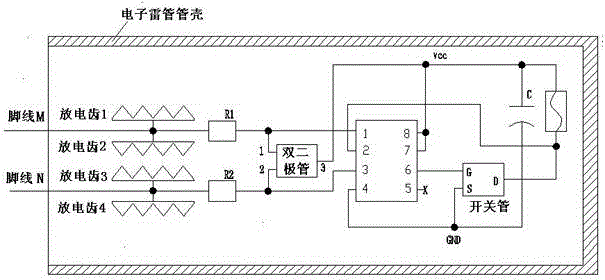
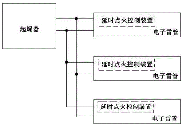
[0064] Embodiment 1: A delay ignition control device, including foot line M, foot line N, integrated with an electrostatic protection device, an electronic delay module, an energy storage device, an ignition head, and a first current limiting resistor R1 on a printed circuit board , The second current limiting resistor R2, anti-reverse connection device.

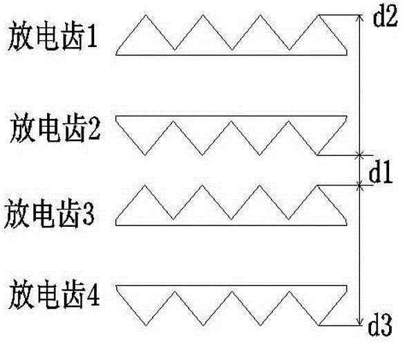
[0065] The electrostatic protection device is installed at the pad of the input terminal of the foot line M and the foot line N and on both sides of the foot line M and the foot line N, before the current limiting resistor, and is used to discharge the static electricity and the foot line of the foot line M and the foot line N input The static electricity input between the shell and the shell; the pad at the input end of the leg line is designed with an electrostatic protection structure; the electronic delay module is used for two-way communication connection with the detonator through the leg line M and the leg line N; when...

Embodiment 2

[0066] Embodiment 2, an electronic detonator with delayed ignition control, including foot wire M and foot wire N, is characterized in that it also includes an electrostatic protection device integrated on the printed board, an electronic time delay module, an energy storage device, an ignition head, The basic detonator, the current limiting device and the basic detonator shell; the electrostatic protection device, the electronic delay module, the energy storage device, the ignition head, and the basic detonator are all arranged inside the basic detonator shell; the electrostatic protection device is arranged on the current limiting device and Between the pads of the input terminal of the foot line M and the foot line N, it is used to discharge the static electricity input by the foot line M and the foot line N, and to discharge the static electricity input by the foot line M, the foot line N and the base detonator shell; the foot The welding pad at the line input end is design...


PUM


Abstract

The invention relates to a delayed ignition device, especially a delayed ignition control device and an electronic detonator for timing initiation. For the problems of the prior art, a delayed ignition control device and an electronic detonator are provided; upon reaching the timing initiation time of the electronic detonator, an energy-storage capacitor can discharge electricity to a detonating fuse head by matching a processor and a switching tube; the component improves the use security of the electronic detonator; meanwhile, in order to prevent the electrostatic influence produced by putting the device into an electronic detonator, an electrostatic protection structure is formed on an electronic detonator cap wire bonding pad accessory in front of a current-limiting resistor. The device comprises a cap wire M and a cap wire N, and comprises an electrostatic protection device, an electronic delay module, an energy-storage device, and a detonating fuse head which are integrated on a printed board. The electrostatic protection device is configured to release static electricity input at any two of the cap wire M, the cap wire N and a detonator shell. The electrostatic protection structure is formed on the cap wire input end bonding pad. The electronic delay module is in both-way communication with an exploder via the cap wire M and the cap wire N.

Description

technical field [0001] The invention relates to a delay ignition device, in particular to a delay ignition control device for timing detonation and an electronic detonator. Background technique [0002] With the development of microelectronic integrated chip technology, the electronic detonator gradually uses the control chip to cooperate with the ignition head to realize the delay control of the electronic detonator. The application number: 201020690573.9, the name is: an electronic delay ignition device. The ignition device has certain defects in terms of production process, product power consumption and electrostatic protection. [0003] The control module has no electrostatic discharge structure, which causes the discharge test of the detonator pins and shells to fail; [0004] The switch is integrated into the chip, which increases the power consumption of the chip. At the same time, the internal resistance of the electronic switch is relatively large, which affects th...

Claims


Application Information

Patent Timeline
Patent Type & Authority Applications(China)
IPC IPC(8): F42C19/12
Inventor 杨黎明赵先锋张永刚黄秀平杨德富李福林刘豪华冯亮
Owner WUXI SHENGJING ELECTRONICS TECH CO LTD
Learn More