Method for measuring time difference proportional displacement of magnetostrictive sensor

A magnetostrictive and displacement measurement technology, applied in the field of sensors, can solve the problems of cumbersome installation, high cost, errors, etc., and achieve the effect of reducing measurement errors and simplifying the device

Inactive Publication Date: 2014-11-19
HOHAI UNIV CHANGZHOU
View PDF9 Cites 5 Cited by
  • Summary
  • Abstract
  • Description
  • Claims
  • Application Information

AI Technical Summary

Problems solved by technology

However, the structure of the device is complex, the installation is cumbersome, and the cost is relatively high, and as long as one of the waveguide wires is abnormal, the effect of reducing interference and noise will be poor, thereby affecting the measurement accuracy
Moreover, when the external clock frequency changes or the material of the waveguide wire changes, the torsional wave velocity changes, resulting in errors, which will also affect the measurement accuracy.
[0007] This shows that above-mentioned existing magnetostrictive displacement sensor displacement measuring method obviously still has inconvenience and defective, and urgently needs to be further improved

Method used


Image

  • Method for measuring time difference proportional displacement of magnetostrictive sensor
  • Method for measuring time difference proportional displacement of magnetostrictive sensor
  • Method for measuring time difference proportional displacement of magnetostrictive sensor

Examples


Embodiment Construction

[0027] The present invention will be further described below in conjunction with the accompanying drawings. The following examples are only used to illustrate the technical solution of the present invention more clearly, but not to limit the protection scope of the present invention.

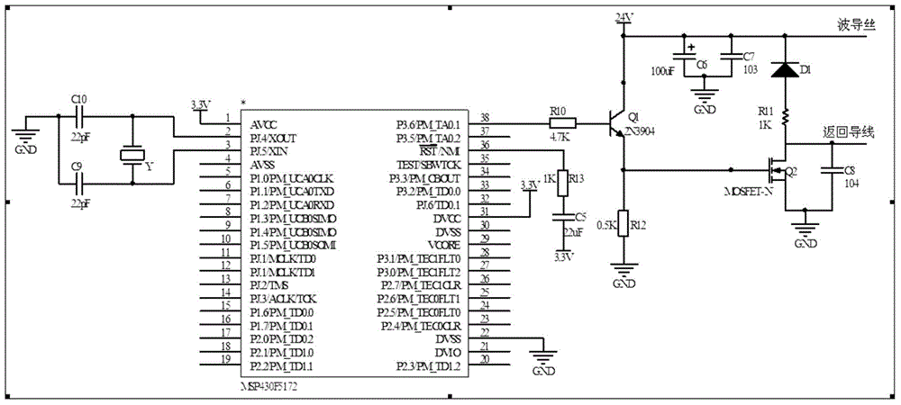
[0028] like figure 1 As shown, the pulse signal generating and receiving module includes a single-chip microcomputer, a triode emitter-follower buffer circuit and an N-channel enhanced MOSFET tube. The single-chip microcomputer adopts an MSP430F5172 chip, and the power supply voltage adopts 3.3V. Through programmable control, through an external crystal oscillator circuit, A pulse signal with a frequency of 1KHz is generated from the P3.6 port of the single-chip microcomputer (depending on the specific measurement displacement of the sensor), and the measurement distance is refreshed once every 1ms. Then the pulse signal is amplified by the triode emitter follower buffer circuit, and then conne...


PUM


Abstract

The invention discloses a method for measuring the time difference proportional displacement of a magnetostrictive sensor. The method is characterized by comprising the following steps: (1) a pulse signal generating and receiving module triggers generation of a periodic excitation originating pulse and sends the periodic excitation originating pulse to the input end of a waveguide wire of a magnetostrictive displacement sensor; (2) the time at which the pulse signal generating and receiving module acquires an excitation signal is recorded as t1, the time at which the signal reaches a coil from a measurement position is recorded as t2, and the time at which the signal returns to the coil through the start end of the waveguide wire is recorded as t3; and (3) inference is made based on the time at which the signal reaches the coil and mathematical principles to obtain the measured displacement X, wherein X=(t2-t1)/(t3-t2)2L. The error amount cancels each other out through the formula when the torsion wave propagation speed and the clock frequency of a system change, thus ensuring the precision of measurement. Moreover, clutter signals are filtered in a targeted mode, and specific noise signals are extracted and used, so that error caused by poor noise reduction effect is cleverly avoided.

Description

technical field [0001] The invention belongs to sensor technology, and in particular relates to a time difference proportional displacement measurement method of a magnetostrictive sensor. Background technique [0002] The magnetostrictive displacement sensor is a non-contact measuring device that uses the Wiedeman effect and the Villary effect of the magnetostrictive material to achieve absolute displacement measurement. It has non-contact, high precision, fast speed, and protection level. It is widely used in machinery, construction, machine tools and other industries due to its excellent characteristics such as high efficiency and low cost. [0003] The research on the displacement measurement of the magnetostrictive displacement sensor mainly focuses on the extraction of the arrival time of the torsional wave and how to reduce the interference signal in the system. The torsional wave propagates at about 2800m / s. According to the measurement principle of the magnetostric...

Claims


Application Information

Patent Timeline
Patent Type & Authority Applications(China)
IPC IPC(8): G01B7/02
Inventor 陆晓春杨欣红黄皎马季邱春毓尹涛
Owner HOHAI UNIV CHANGZHOU
Why Eureka
Try Eureka