Relaying method based on uniquely decodable code
A forwarding method and decoding technology, applied in radio relay systems, active electrical relay systems, digital transmission systems, etc., can solve the problems of reduced system throughput, high bit error rate, and increased number of time slots. The effect of improving throughput and good channel capacity
- Summary
- Abstract
- Description
- Claims
- Application Information
AI Technical Summary
Problems solved by technology
Method used
Image
Examples
specific Embodiment approach 1
[0021] Specific implementation mode 1: The uniquely decodable-based relay forwarding method of this implementation mode is implemented in the following steps:
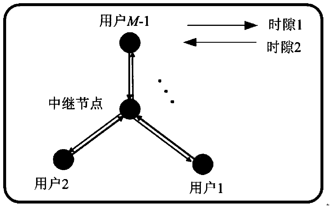
[0022] For an M-node relay system, including M-1 user nodes and a relay node, any user node uses two time slots to obtain information sent by any other user node through the relay node;
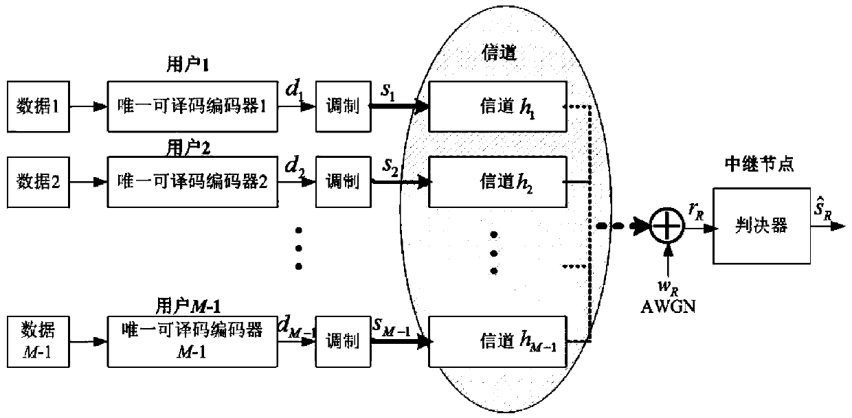
[0023] Among them, in the first time slot, all M-1 user nodes will send the uniquely decodable and encoded information to the relay node;
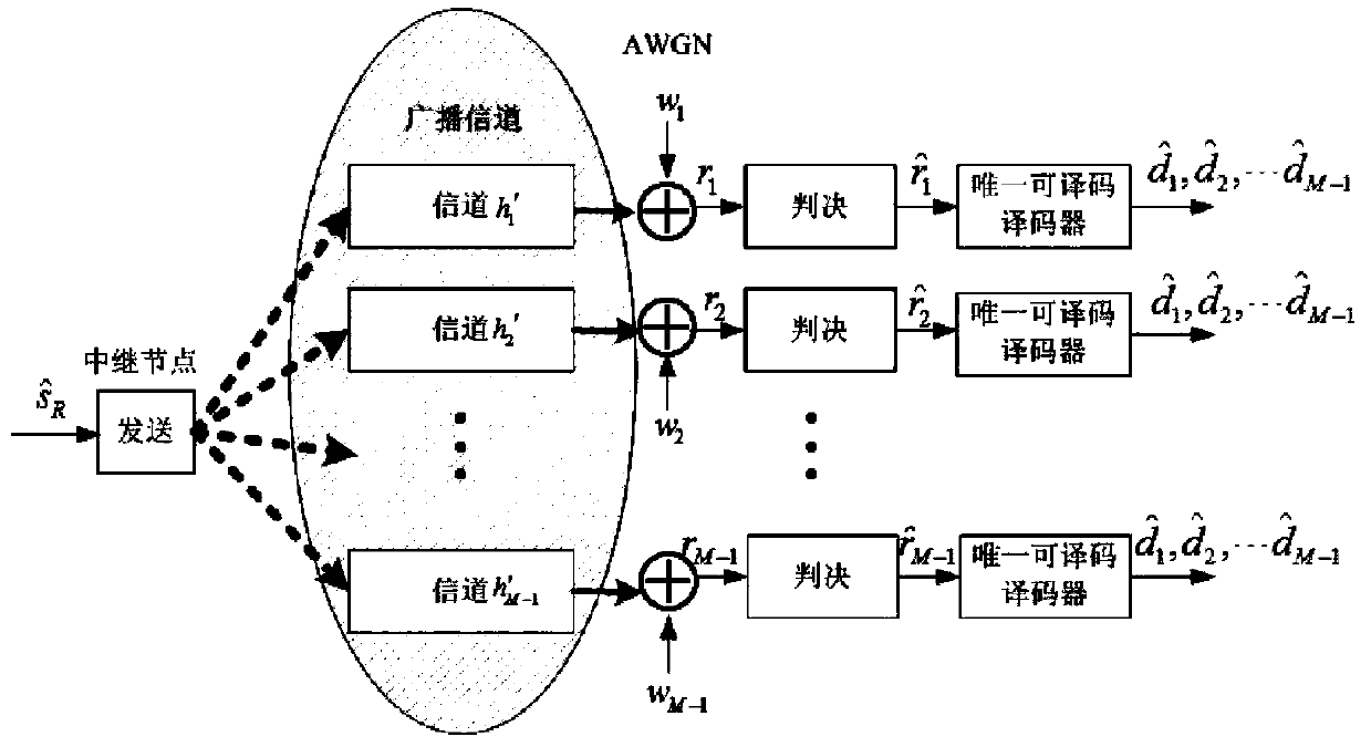
[0024] Then in the second time slot, the relay node sends the judged result in the form of broadcast after judgment and forwarding, and each user node matches the received broadcast information with a unique decodable code, thereby Obtaining the information sent by other user nodes completes the unique decodable-based relay forwarding method.
specific Embodiment approach 2
[0025] Specific implementation mode two: the difference between this implementation mode and specific implementation mode one is: the execution steps of the first time slot are as follows:
[0026] Step 1, all M-1 user nodes pass the effective information data of the user nodes through the unique decodable encoder to obtain the encoded code word d 1 ,d 2 ,...,d M-1 ; Wherein, each of the codewords is an n-dimensional vector;
[0027] Step 2, the M-1 codewords d obtained in step 1 1 ,d 2 ,...,d M-1 , respectively modulated into s 1 ,s 2 ,...,s M-1 , where s i Represents the modulated symbol sent by the i-th user in the first time slot, where i=1,2,...,M-1;
[0028] Step 3, the s in step 2 1 ,s 2 ,...,s M-1 through the channel h 1 ,h 2 ,...,h M-1 , the signal r received at the relay node R ;
[0029] in, r R = Σ i = 1 M ...
specific Embodiment approach 3
[0037] Specific implementation mode three: the difference between this implementation mode and specific implementation modes one or two is that: the execution steps of the second time slot are as follows:
[0038] Step one, will Broadcast through the channel h' through the relay node 1 ,h′ 2 ,... h′ M-1 sent out; where, the channel h' 1 ,h′ 2 ,... h′ M-1 , if h′ 1 =h' 2 =...=h' M-1 =1, then in the second time slot, the broadcast channel between the relay node and each user is the Rayleigh channel;
[0039] If the channel h' 1 ,h′ 2 ,... h′ M-1 Both obey the independent and identically distributed Rayleigh distribution, then in the second time slot, the broadcast channel of the relay node and each user is the Rayleigh channel;
[0040]Step 2, among all M-1 users, send the received broadcast information r 1 ,r 2 ,...,r M-1 verdict Among them, r i Represents the signal received by the i-th user in the second time slot, then r i (1≤i≤M-1) is
[0041] ...
PUM
 Abstract
Description
Claims
Application Information
 - R&D
- Intellectual Property
- Life Sciences
- Materials
- Tech Scout
- Unparalleled Data Quality
- Higher Quality Content
- 60% Fewer Hallucinations
Browse by: Latest US Patents, China's latest patents, Technical Efficacy Thesaurus, Application Domain, Technology Topic, Popular Technical Reports.
© 2025 PatSnap. All rights reserved.Legal|Privacy policy|Modern Slavery Act Transparency Statement|Sitemap|About US| Contact US: help@patsnap.com


