Plasma catalysis air purification device

An air purification device and plasma technology, applied in separation methods, dispersed particle separation, chemical instruments and methods, etc., can solve problems such as unavoidable plasma and difficult to solve high power consumption of plasma, so as to improve air purification effect and solve The problem of high power consumption and the effect of small air resistance

Inactive Publication Date: 2014-11-26
SHENZHEN PUREMATE TECH +1
View PDF8 Cites 3 Cited by
  • Summary
  • Abstract
  • Description
  • Claims
  • Application Information

AI Technical Summary

Problems solved by technology

Although the patent mentions that a dielectric barrier discharge structure can be used, the dielectric barrier discharge structure described in it only adds an insulating medium between the pin plate corona structures, and this structure also cannot avoid the problem that the plasma is only generated at the tip of the electrode
In addition, in the above two patents, the treatment of the catalyst by the plasma needs to treat the entire catalyst bed at the same time, which is difficult to solve the disadvantage of high power consumption of the plasma

Method used


Image

  • Plasma catalysis air purification device
  • Plasma catalysis air purification device
  • Plasma catalysis air purification device

Examples


Embodiment 1

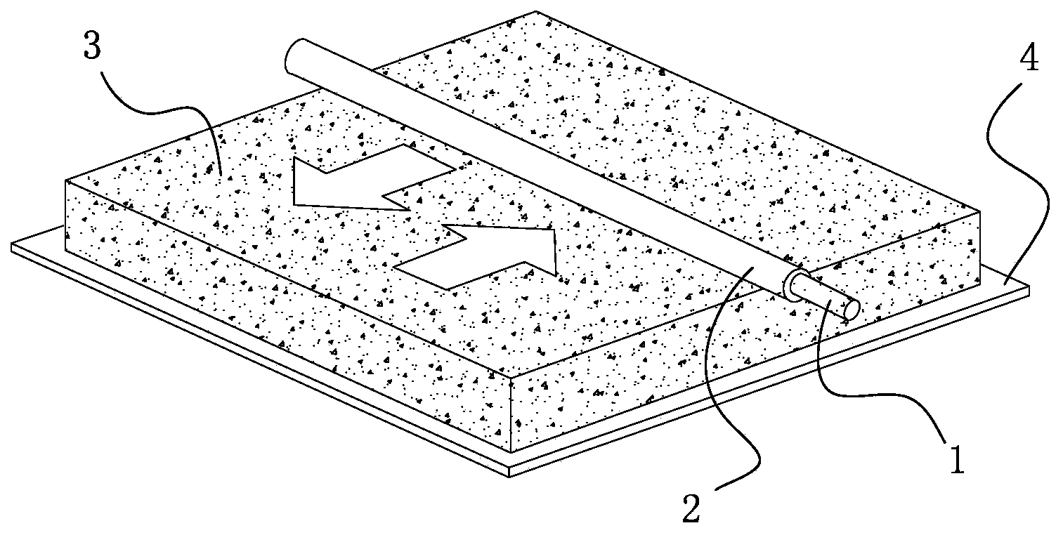
[0028] Such as figure 1 As shown, the plasma catalytic air purification device of this embodiment includes a first electrode 1 , an insulating medium 2 , a catalyst bed 3 and a second electrode 4 . Wherein, the first electrode 1 is a stainless steel rod with a diameter of 3 mm; the insulating medium 2 is a quartz tube with an inner diameter of 3 mm and a thickness of 1 mm; the catalyst bed 3 is a bed of noble metal catalyst pellets with a bed thickness of 10 mm; The second electrode 4 is an 80-mesh metal mesh.

[0029] The simulated air with a toluene concentration of 150mg / m3 is passed into the plasma catalytic purification device, and the AC high voltage of 2kHz is applied to the first electrode 1 and the second electrode 4, then the gas between the first electrode 1 and the second electrode 4 It will be broken down to form a dielectric barrier discharge plasma; the driving mechanism (such as a motor) drives the first electrode 1 to move horizontally in the direction of the...

Embodiment 2

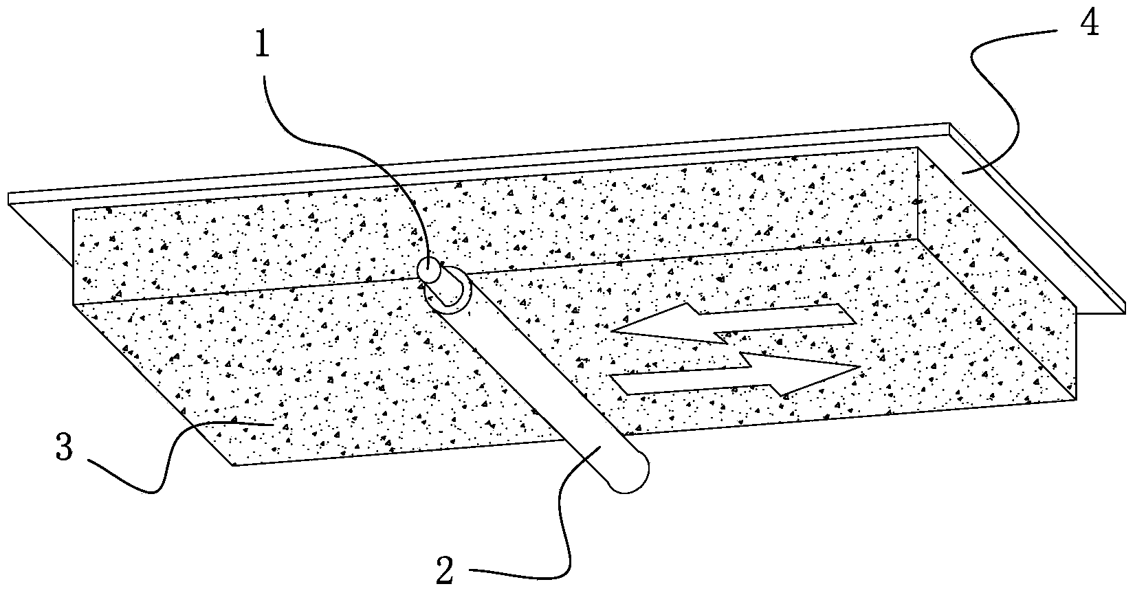
[0031] Such as figure 2 As shown, the difference from Example 1 is that the first electrode 1 in this example is placed below the catalyst bed 3 , the second electrode 4 is placed above the catalyst bed 3 , and the rest of the conditions are the same as in Example 1.

Embodiment 3

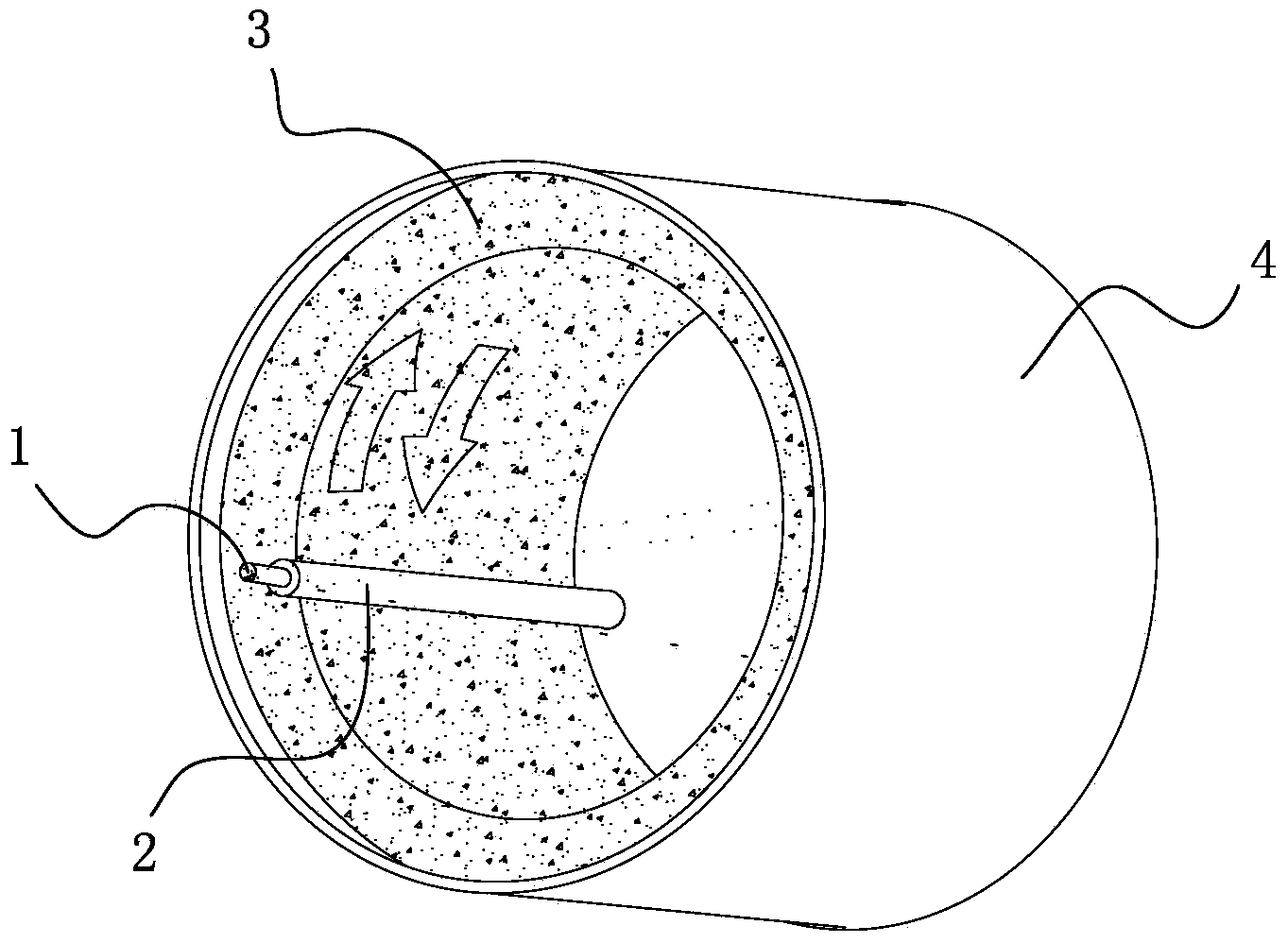
[0033] Such as image 3 As shown, the difference from Embodiment 1 is that the second electrode 4 in this embodiment is changed to a cylindrical shape, and the movement mode of the first electrode 1 is rotated around the axis at 2 r / min. The rest of the conditions are the same as in Embodiment 1. It is also possible to completely oxidize toluene to carbon dioxide and water.


PUM

PropertyMeasurementUnit
Widthaaaaaaaaaa
Particle sizeaaaaaaaaaa
Thicknessaaaaaaaaaa

Abstract

The invention discloses a plasma catalysis air purification device which comprises a first electrode and a second electrode used for generating plasma, wherein an insulating medium and a catalyst bed layer are arranged between the first electrode and the second electrode; relative motion is generated between the first electrode and the second electrode. With the adoption of the relative motion generated between the first electrode and the second electrode, a plasma discharge area is driven to sequentially act on the whole catalyst bed layer, organic pollutants stored on the catalyst are completely oxidized into carbon dioxide and water through plasma active species, the device is high in treated air quantity, low in power consumption and low in air resistance, and the air purification effect is greatly improved. The plasma discharge area is driven to move through the relative motion of the electrodes, and the whole catalysts are sequentially treated. Therefore, the power consumption is obviously reduced, the problem of high plasma power consumption in the process of simultaneously treating the whole catalyst bed layer is solved, and the relative motion of the electrodes has the advantages of discharge stability, uniformity and high efficiency.

Description

technical field [0001] The invention relates to low-temperature plasma environment application technology, in particular to a plasma catalytic air purification device. Background technique [0002] The use of building decoration materials and organic solvents will lead to the release of volatile organic pollutants, which will seriously pollute people's living environment and cause various diseases and complications. Atmospheric pressure low-temperature plasma is a new technology for indoor air purification. Low-temperature plasma has very high energy selectivity, electrons are preferentially accelerated to 1-10eV, and the gas temperature is not high, even kept at room temperature, electrons and gas Molecular collision produces a large number of active species through excitation and dissociation process, which can remove pollutants at low temperature, which has the advantages of fast and efficient. However, pure plasma is used for the removal of pollutants, which requires hi...

Claims


Application Information

Patent Timeline
IPC IPC(8): B01D53/86B01D53/44
CPCB01D53/44B01D53/86
Inventor 朱爱民刘景林李小松严义清李祥武严方升
Owner SHENZHEN PUREMATE TECH
Why Eureka
Try Eureka