Hydroenergy fuel combustion device

A combustion device and fuel technology, applied in gas fuel burners, burners, combustion methods, etc., can solve the problems of poor practicability and high cost, and achieve the effect of increasing the area, increasing the combustion temperature, and being conducive to full combustion

Inactive Publication Date: 2014-11-26
石增辉
View PDF4 Cites 0 Cited by
  • Summary
  • Abstract
  • Description
  • Claims
  • Application Information

AI Technical Summary

Problems solved by technology

Water splitting can be achieved by various methods such as electrolysis, chemistry, microorganisms, and solar energy, but the cost is high and the practicability is poor, so it is impossible to use it in real industry

Method used


Image

  • Hydroenergy fuel combustion device

Examples


Embodiment 1

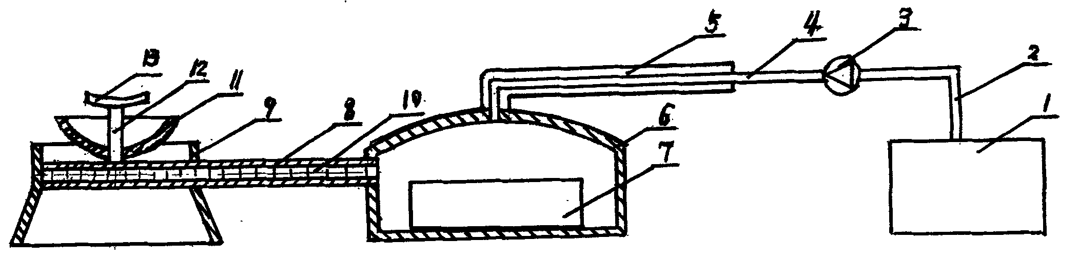
[0010] Embodiment 1, a water energy fuel combustion device, consists of a water tank 1, a water pipe 2, a metering pump 3, a water inlet pipe 4, a temperature resistance pipe 5, a gasification catalytic chamber 6, a catalyst 7, a mixed flow pipe 8, an absorption cover 9, a high temperature Catalyst 10, reflection cover 11, gas nozzle 12, flame dispersion plate 13, wherein the water tank 1 is connected to the metering pump 3 through the water pipe 2, the metering pump 3 is connected to the water inlet pipe 4, the water inlet pipe 4 is covered with a temperature resistance pipe 5, and connected to the gas Gasification catalytic chamber 6, catalyst 7 is installed at the bottom of gasification catalytic chamber 6, one end of mixing pipe 8 is connected to the side wall of gasification catalytic chamber 6, and the other end is connected to gas nozzle 12 through absorption cover 9, high temperature catalyst 10 is installed on the inner wall of mixing pipe 8, The reflection cover 11 is...

Embodiment 2

[0014] Embodiment 2, a water energy fuel combustion device, consists of a water tank 1, a water pipe 2, a metering pump 3, a water inlet pipe 4, a temperature resistance pipe 5, a gasification catalytic chamber 6, a catalyst 7, a mixed flow pipe 8, an absorption cover 9, a high temperature Catalyst 10, reflection cover 11, gas nozzle 12, flame dispersion plate 13, wherein the water tank 1 is connected to the metering pump 3 through the water pipe 2, the metering pump 3 is connected to the water inlet pipe 4, the water inlet pipe 4 is covered with a temperature resistance pipe 5, and connected to the gas Gasification catalytic chamber 6, catalyst 7 is installed at the bottom of gasification catalytic chamber 6, one end of mixing pipe 8 is connected to the side wall of gasification catalytic chamber 6, and the other end is connected to gas nozzle 12 through absorption cover 9, high temperature catalyst 10 is installed on the inner wall of mixing pipe 8, The reflection cover 11 is...


PUM


Abstract

The invention belongs to the technology of industrial combustion, and particularly relates to a hydroenergy fuel combustion device. The hydroenergy fuel combustion device is composed of a metering pump, a gasification catalyst chamber, catalysts, a gas nozzle, a flame dispersion disc and the like. A water tank is connected with the metering pump through a water pipe, the metering pump is connected with a water inlet pipe, the water inlet pipe is coated with a resistance temperature pipe, and is connected to the gasification catalyst chamber, the catalysts are arranged at the bottom of the gasification catalyst chamber, one end of a flow mixing pipe is connected to the side wall of the gasification catalyst chamber, the other end of the flow mixing pipe is communicated with the gas nozzle through an absorbing cover, the high-temperature catalysts are contained in the inner wall of the flow mixing pipe, a reflection cover passes through the gas nozzle and is fixed to the root of the gas nozzle, and the flame dispersion disc is arranged on the top of the gas nozzle. The hydroenergy fuel combustion device is arranged on the rear portion of a main combustion area of a boiler, the high temperature in a combustion chamber of the boiler is utilized for splitting water molecules, due to the fact that hydroenergy participates in combustion, full combustion of fuel is benefited, and the energy-saving environment-friendly index of the boiler is further improved. The hydroenergy fuel combustion device is suitable for boiler transformation and has the advantages of being efficient, saving energy and being environmentally friendly.

Description

technical field [0001] The invention belongs to industrial combustion technology, more precisely, it is a water energy fuel combustion device. Background technique [0002] Water is composed of hydrogen and oxygen elements. A small amount of hydrogen and oxygen can be decomposed at high temperature. As the temperature rises, more hydrogen and oxygen can be decomposed. Hydrogen is a high-calorific value non-polluting high-quality fuel. If water is decomposed under economical conditions to produce hydrogen, and then burned to generate considerable heat energy, such water will become a new energy source with the most abundant resources and the cheapest cost. Water splitting can be achieved by various methods such as electrolysis, chemistry, microorganisms, and solar energy, but the cost is high and the practicability is poor, so it is impossible to use it in real industry. At present, boilers are still widely used in the world. There is a naturally formed high-temperature envi...

Claims


Application Information

Patent Timeline
Patent Type & Authority Applications(China)
IPC IPC(8): F23D14/00F23D14/46
Inventor 石增辉
Owner 石增辉
Why Eureka
Try Eureka