Mixed asymmetric permanent magnet rotor

A permanent magnet rotor, asymmetric technology, applied in the direction of magnetic circuit rotating parts, magnetic circuit shape/style/structure, electrical components, etc., can solve the problems of motor torque ripple, unstable operation, waste of resources, etc. Small torque ripple and cogging torque, improving stability and efficiency, avoiding noise and vibration effects

Inactive Publication Date: 2014-11-26
SOUTHEAST UNIV
View PDF3 Cites 10 Cited by
  • Summary
  • Abstract
  • Description
  • Claims
  • Application Information

AI Technical Summary

Problems solved by technology

[0002] With the rise of rare earth permanent magnet materials, the manufacturing cost of permanent magnet rotors increases
Although the traditional permanent magnet rotor structure uses high-performance permanent magnet materials to obtain high magnetic energy density, it fails to fully utilize the permanent

Method used


Image

  • Mixed asymmetric permanent magnet rotor

Examples


Embodiment Construction

[0014] The present invention will be further explained below in conjunction with the accompanying drawings.

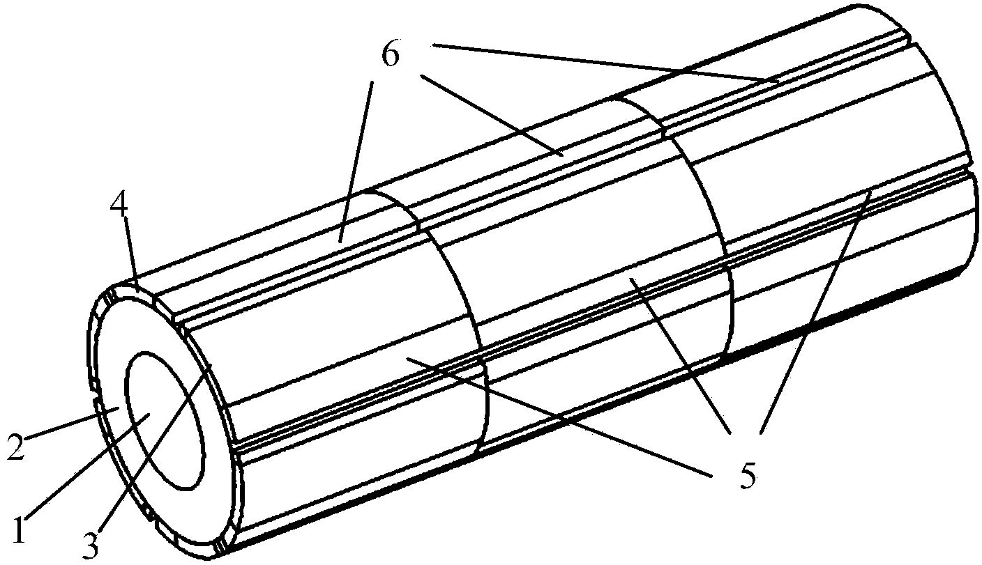
[0015] Such as figure 1 As shown, a hybrid asymmetric permanent magnet rotor includes a rotating shaft 1, a rotor core 2 and a permanent magnet. The rotating shaft 1 passes through the shaft hole of the rotor core 2 and is fastened together with the rotor core 2. The permanent magnet Paste on the surface of the rotor core 2. In this embodiment, the permanent magnets include two pairs of pole permanent magnets, and the pole arc coefficient is 0.6, including N-pole permanent magnets 3 and S-pole permanent magnets 4 of NdFeB materials, and N-pole permanent magnets 5 and S-pole permanent magnets of ferrite materials. S pole permanent magnet 6. N-pole permanent magnet 3 and S-pole permanent magnet 4 of NdFeB material and N-pole permanent magnet 5 and S-pole permanent magnet 6 of ferrite material are tile-shaped permanent magnets magnetized along the radial direction.

[...


PUM


Abstract

The invention discloses a mixed asymmetric permanent magnet rotor which aims at solving the problems that material cost is excessively high, and torque ripples need to be reduced. The rotor comprises a rotating shaft, a rotor core and a permanent magnet. The permanent magnet is pasted to the surface of the rotor core in a sectional-type-structure mode and is of a spliced structure made of neodymium iron boron materials and ferrite materials, each pole of the permanent magnet is formed by three permanent magnet bodies, the middle of the permanent magnet is made of the neodymium iron boron materials, and the two ends of the permanent magnet are made of the ferrite materials. When the rotor rotates, air gap flux density is in a step shape which is closer to the sine wave, and the torque ripples are effectively reduced. The mixed asymmetric permanent magnet rotor is mainly used for a linear rotating converter, shaking and losses of the converter can be lowered with the rotor serving as a rotating part, and meanwhile the stability of the converter is improved.

Description

technical field [0001] The invention relates to a hybrid asymmetrical permanent magnet rotor, which belongs to the technical field of motors. Background technique [0002] With the rise of rare earth permanent magnet materials, the manufacturing cost of permanent magnet rotors increases. Although the traditional permanent magnet rotor structure uses high-performance permanent magnet materials to obtain high magnetic energy density, it fails to fully utilize the permanent magnetic material, resulting in waste of resources; while obtaining high magnetic energy density, the traditional permanent magnet motor rotor structure will make The motor produces torque pulsation, which causes the motor to vibrate, make noise, run unstable, and affect the operating efficiency of the motor. [0003] The hybrid asymmetrical permanent magnet rotor is used, and part of the permanent magnets are made of low-remanence and cheap permanent magnet materials, which do not have much impact on the a...

Claims


Application Information

Patent Timeline
IPC IPC(8): H02K1/27H02K29/03
Inventor 付兴贺王标林明耀
Owner SOUTHEAST UNIV
Why Eureka
Try Eureka