
Ultrasound knife head and ultrasound knife

An ultrasonic knife and knife head technology, which is used in anatomical instruments, medical science, surgery, etc., can solve the problem that the reliability of the sound wave generator and the knife head cannot be effectively guaranteed, and achieves a fast and convenient knife head angle, reliable connection, and balanced The effect of ease of disassembly

Active Publication Date: 2014-12-03
REACH SURGICAL
View PDF5 Cites 10 Cited by
  • Summary
  • Abstract
  • Description
  • Claims
  • Application Information

AI Technical Summary

Problems solved by technology

In this structure, although a protective device for limiting the torque is built in and is not easy to lose, it still has the same problem as the torque wrench mentioned above in terms of reliability.
Because the slipping between the retaining ring and the elastic ring still depends on the material deformation of the retaining ring and the elastic ring itself, factors such as the manufacturing error of the retaining ring and the elastic ring, the performance difference of the material, and the wear of the material during use will greatly affect the protection. The output torque of the device cannot effectively guarantee the reliability of the connection between the sonic generator and the cutter head

Method used


Image

  • Ultrasound knife head and ultrasound knife
  • Ultrasound knife head and ultrasound knife
  • Ultrasound knife head and ultrasound knife

Examples


Embodiment Construction

[0039] The present invention will be described in further detail below in conjunction with the accompanying drawings and specific embodiments, so that those skilled in the art can more clearly understand other advantages and effects of the present invention.

[0040] It should be noted that the structures, proportions, sizes, etc. shown in the drawings of the specification are only used to cooperate with specific implementation methods, so that those skilled in the art can understand the concept of the present invention more clearly, and are not intended to limit the scope of protection of the present invention. . Any structural modification, change in proportional relationship or size adjustment should still fall within the protection scope of the present invention, provided that it does not affect the function and purpose of the present invention. For ease of understanding, the relative positional relationship of each component is described according to the layout of the dra...


PUM


Abstract

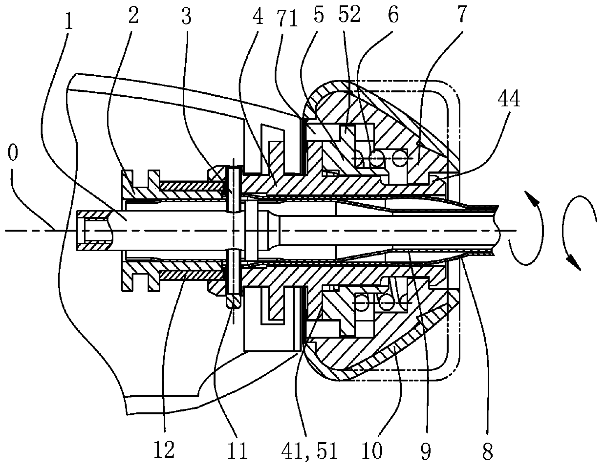
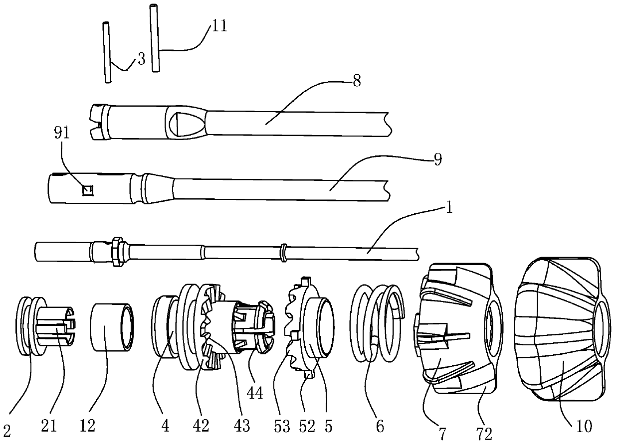
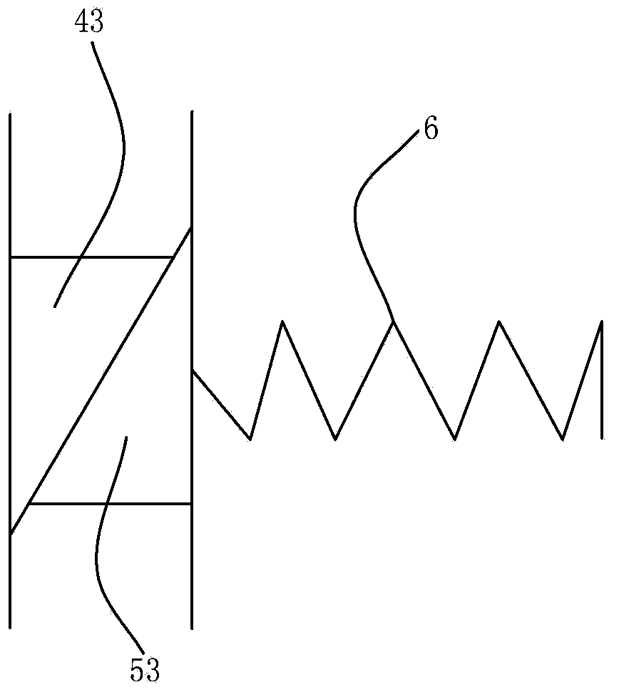
Disclosed is an ultrasonic knife head (100), wherein a centre pole (1) of the ultrasonic knife head (100) can rotate around an axis and thread-connect to a driving handle (200), a power transmission device is fixedly connected to the centre pole (1), and the power transmission device has at least one bearing surface (41); the rotating device comprises a crowding mechanism and a rotation driving mechanism, wherein the rotation driving mechanism has at least one force applying surface (51), one bearing surface (41), wherein the force applying surface (51) is a surface which is not perpendicular to the axis, and the surfaces are capable of engaging with each other, and the crowding mechanism provides a thrust pressure to press the rotation driving mechanism against the power transmission device, thereby engaging the force applying surface (51) with the bearing surface (41), and the thrust pressure is set to be the thrust pressure the rotation driving mechanism can overcome when the interaction force between the force applying surface (51) and the bearing surface (41) is greater than the predetermined value, disengaging the force applying surface (51) and the bearing surface (41). As long as the thrust pressure is set reasonably, the set torque can be delivered, and when the torque is greater than the set value, the rotation driving mechanism will overcome the thrust pressure and slip, thereby limiting the delivery of the torque and providing protection. The present invention also provides an ultrasonic knife comprising the ultrasonic knife cutting head (100).

Description

technical field [0001] The invention relates to an ultrasonic scalpel and a cutter head structure of the ultrasonic scalpel, in particular to a cutter head and an ultrasonic scalpel integrated with a torque limiting device. Background technique [0002] Ultrasonic knife generally includes ultrasonic knife host, driving handle and connection, knife head and foot switch or manual switch, etc., and the knife head includes handle, knife rod and knife tip, etc. When the switch is activated, the main engine outputs the electric energy at the resonant frequency of the vibration system to the drive handle, and the drive handle converts the electric energy into ultrasonic vibration mechanical energy and outputs it to the cutter head. Vaporization of water, breakage of protein hydrogen bonds, disintegration of cells, tissue incision or coagulation, so as to achieve the purpose of cutting tissue and hemostasis. [0003] The cutter head of the ultrasonic scalpel is connected to the dri...

Claims


Application Information

Patent Timeline
IPC IPC(8): A61B17/3211
CPCA61B90/03A61B17/320068A61B17/320092A61B17/3211A61B2090/031A61B2017/2929A61B2017/320093A61B2017/320095A61B34/30
Inventor 沈美君郝吾干杨晓峰钟学平孙秋香陈启章方云才汪炬
Owner REACH SURGICAL
Learn More