Coil part and manufacturing method thereof

A technology for coil components and manufacturing methods, applied in coil manufacturing, coils, transformer/inductor components, etc., can solve the problems of low DC resistance, reduce DC resistance, etc., to improve adhesion, improve reliability, high performance and Reliable effect

Inactive Publication Date: 2014-12-03
TDK CORPARATION
View PDF6 Cites 10 Cited by
  • Summary
  • Abstract
  • Description
  • Claims
  • Application Information

AI Technical Summary

Problems solved by technology

However, for example, common mode filters and power supply coils (power inductors) require low DC resistance. If the thickness of the coil pattern is too low, the DC resistance increases. Therefore, it is desirable to reduce the DC resistance by making the coil pattern as thick as possible.

Method used


Image

  • Coil part and manufacturing method thereof
  • Coil part and manufacturing method thereof
  • Coil part and manufacturing method thereof

Examples


Embodiment Construction

[0084] Hereinafter, preferred embodiments of the present invention will be described in detail with reference to the drawings.

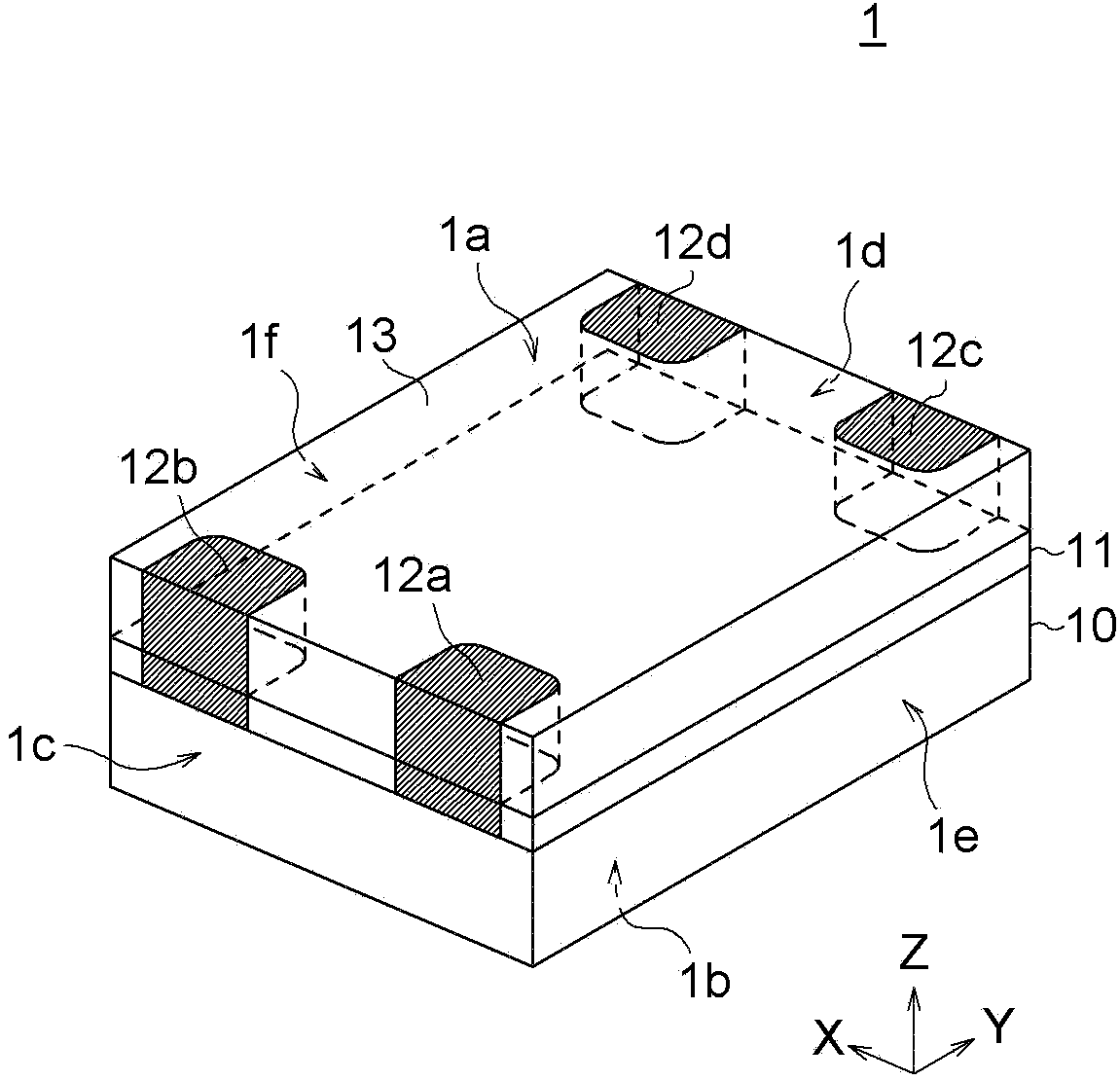
[0085] figure 1 It is a perspective view which shows the external structure of the coil component 1 which concerns on 1st Embodiment of this invention.

[0086] Such as figure 1 As shown, the coil component 1 of the present embodiment is a common mode filter having a four-terminal structure, and includes a substrate 10, a functional layer 11 provided on the upper surface of the substrate 10, and first to fourth solder joints provided on the upper surface of the functional layer 11. The pad electrodes 12a to 12d and the cover layer 13 provided on the upper surface of the functional layer 11 other than the formation positions of the pad electrodes 12a to 12d.

[0087] As shown in the figure, the coil component 1 is a substantially rectangular parallelepiped surface-mount chip component having an upper surface 1a, a bottom surface 1b, two side surface...


PUM

PropertyMeasurementUnit
thicknessaaaaaaaaaa
thicknessaaaaaaaaaa
thicknessaaaaaaaaaa

Abstract

The invention provides a coil part which is characterized in that even if a coil pattern is made in a high aspect ratio, there is no shifting or thermal peeling problems, and the performance and the reliability are high. The coil part (1) is provided with coil layers (14a-14d), and each coil layer (14a-14d) is provided with an insulating layer (15a-15d), a framework layer (16a-16d) formed on the insulating layer (15a-15d), and a conductor layer (17a-17d) which is formed on the same plane as the framework layer (16a-16d) and includes a spiral conductor (19-22). Each framework layer (16a-16d) comprises an opening image (18a-18d) including a negative pattern of a coil pattern, and the spiral conductors (19-22) are formed in the opening image (18a-18d). The spiral conductors (19-22) are provided with seed layers (30) for covering the bottom surfaces and the inner side surfaces of the opening images (18a-18d), and clad layers (31) arranged on the surfaces of the seed layers (30).

Description

technical field [0001] The present invention relates to a coil component and its manufacturing method, and more particularly to a coil component having a planar coil structure and its manufacturing method. Background technique [0002] A planar coil structure capable of miniaturization and thinning is adopted as a surface mount type coil component (for example, refer to Patent Document 1). The planar coil structure is a structure in which, for example, a spiral planar coil pattern is formed on a substrate. With recent advances in manufacturing technology, coil patterns can be made extremely small and have narrow pitches. However, for example, common mode filters and coils for power supplies (power inductors) are required to have low DC resistance. If the thickness of the coil pattern is too low, the DC resistance increases. Therefore, it is desirable to reduce the DC resistance by making the coil pattern as thick as possible. [0003] Conventionally, a so-called semi-addit...

Claims


Application Information

Patent Timeline
Patent Type & Authority Applications(China)
IPC IPC(8): H01F5/00H01F27/28H01F27/30H01F41/04
CPCH01F17/0013H01F27/2804H01F41/04
Inventor 西川朋永奥村武史伊藤知一石川直纯松田沙织
Owner TDK CORPARATION
Why Eureka
Try Eureka