Control apparatus and control method for maintaining stable voltage of conflux DC bus in distributed power generation system

A DC bus voltage and distributed power generation technology, which is applied in the direction of parallel operation of DC power supplies, can solve the problems of DC bus voltage fluctuations and unfavorable system operation, and achieve the effect of smooth switching

Active Publication Date: 2014-12-03
HARBIN ENG UNIV
View PDF4 Cites 13 Cited by
  • Summary
  • Abstract
  • Description
  • Claims
  • Application Information

AI Technical Summary

Problems solved by technology

[0003] On the other hand, in order to obtain more electric energy from nature, each power generation device may set a maximum power capture (MPPT, Maximum Power Point Tracking) algorithm according to its actual situation, and each device uses a current mode (approximately controllable current source) to The busbar injects energy, so in the independent microgrid mode, it will cause the voltage fluctuation of the DC busbar, which is not conducive to the operation of the whole system

Method used


Image

  • Control apparatus and control method for maintaining stable voltage of conflux DC bus in distributed power generation system
  • Control apparatus and control method for maintaining stable voltage of conflux DC bus in distributed power generation system
  • Control apparatus and control method for maintaining stable voltage of conflux DC bus in distributed power generation system

Examples


Embodiment Construction

[0026] The following examples describe the present invention in more detail.

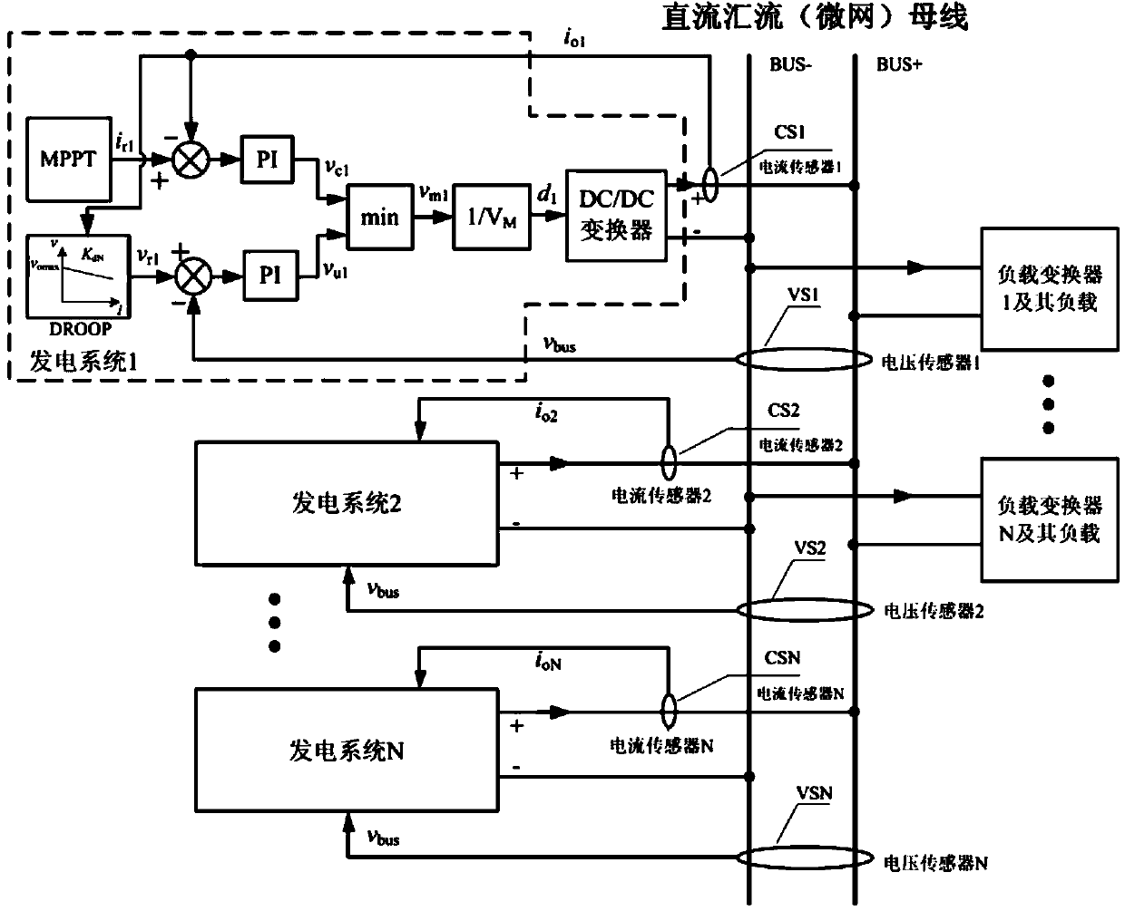
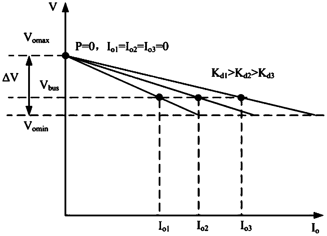
[0027] combine figure 1 and figure 2 , taking the power generation system 1 as an example for illustration.

[0028] attached figure 1 Among them, CS1-CSN are current HALL sensors, which are used to detect the output current of each DC / DC converter module. VS1-VSN are voltage HALL sensors, which are used in each power generation system to detect the voltage value of the DC return bus. MPPT is the maximum power point tracking module, which generates the command current value i that can obtain the maximum power according to the operation of the power generation device (such as solar cells, wind generators, etc., not shown in the figure) r1 , this value is the same as the actual output current i of the power generation system o1 The deviation is used for PI regulation to generate a control signal v c1 ; attached figure 2 DROOP in is the voltage droop module, and its droop coefficient is K d1 ...


PUM


Abstract

The invention provides a control apparatus and control method for maintaining stable voltage of a conflux DC bus in a distributed power generation system. In order to enable the current transformers of multiple power generation devices to realize parallel operation under the condition that there is no interconnection line communication, voltage instruction signals are obtained through calculation according to a preset sagging characteristic by actual output currents, current instruction signals are given according to actual conditions by an MPPT algorithm or a system, two control signals obtained through operation of a voltage control loop and a current control loop are sent to the minimum taking link of CPU control software, and the output of the link is used for PWM to ensure no overvoltage in case of a current control mode and ensure no overcurrent in case of a voltage control mode, such that smooth switching of multiple electric power converting devices between the current control mode and the voltage control mode is realized, and under the condition that there are no interconnection communication lines, multiple converters can realize stable parallel output according to power which can be obtained by themselves.

Description

technical field [0001] The invention relates to a DC bus voltage stabilization control technology in a distributed power generation system. Background technique [0002] A distributed power generation system may include multiple photovoltaic solar power generation devices, wind power generation devices, ocean current power generation devices, and biomass power generation devices. Under the conditions of DC bus or DC microgrid, these devices transmit DC power to the busbar. Since the design capacities of these power generating devices are different, even if the capacity is the same, at the same time, due to the influence of weather and environmental factors, there may be large differences in the output power of each generating device. For example, solar power generation has no output at night, while wind power generation is available. [0003] On the other hand, in order to obtain more electric energy from nature, each power generation device may set a maximum power capture...

Claims


Application Information

Patent Timeline
Patent Type & Authority Applications(China)
IPC IPC(8): H02J1/12
Inventor 游江罗耀华马佳睿张敬南巩冰孟繁荣
Owner HARBIN ENG UNIV
Why Eureka
Try Eureka