

Electric control type air pressure subsoiler
A subsoiler and electronically controlled technology, which is applied in the field of electronically controlled pneumatic subsoilers, can solve the problems of high energy consumption and poor subsoiling effect, so as to increase grain production, deepen the depth of subsoiling, and improve the effect of subsoiling Effect
- Summary
- Abstract
- Description
- Claims
- Application Information
AI Technical Summary
Problems solved by technology
Method used
Image

Examples
Embodiment 1
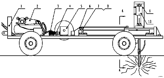
[0024] The frame 1 is a frame welded by rectangular steel. The upper surface of the frame 1 is covered with iron plates. Mounting holes are provided at the places where the intermittent mechanism, guide rail sliding mechanism and other components are placed. Other components are fixedly connected on the frame 1. The front end of the frame 1 has connecting ears, which are connected with the traction device at the rear of the tractor through pin shafts, and the bottom of the frame 1 is equipped with traveling wheels. During work, the frame 1 can be pulled by a tractor to bear the weight of each component and ensure the installation position of the component.
Embodiment 2
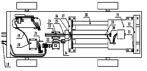
[0026] Intermittent mechanism is made up of hydraulic motor 3, shaft coupling 4, speed reducer 5, clutch 22, bearing block 23, reel shaft 24 and reel 25. The hydraulic motor 3 is fixed in the middle of the frame 1, and its input port is connected with the hydraulic power output port of the tractor; the reducer 5 is fixed in the middle of the frame 1, and its input shaft is connected with the output shaft of the hydraulic motor 3 through a coupling 4. The output shaft is connected with the reel shaft 24 through the clutch 22; the reel 25 is connected with the pulley 31 through the steel wire 29; During the working process, the hydraulic motor 3 drives the reel 25 to rotate through the coupling 4, the reducer 5 and the clutch 22, thereby driving the pulley 31 to move forward. The barrel 25 stops driving the trolley 31 and the forward movement of the trolley 31 stops. After the clutch 22 breaks away from idling for a certain period of time, it is automatically closed under the a...
Embodiment 3
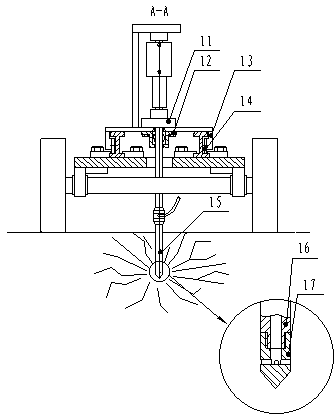
[0028] Guide rail sliding mechanism is made up of slide rail 28, tackle 31, and slide rail 28 is fixed on the rear end of frame 1. Pulley 14 is equipped with at two ends of tackle 31, and tackle 31 is assembled on the slide rail 28. During the working process, the tackle 31 slides intermittently on the H-shaped slide rail 28 , and the pulley 14 positions the tackle 31 , thereby realizing the smooth sliding of the tackle 31 on the slide rail 28 .
PUM
 Abstract
Description
Claims
Application Information